EVF/EVH User Manual EVF-1121S EVF-1151S EVF-1181S EVF-2121S EVF-2151D EVF-1122S (All Patterns) EVF-1122D (All Patterns) EVF-1152S (All Patterns) EVF-1152D (All Patterns) EVH-1152S (All Patterns) EVH-1152D (All Patterns) Electro-Voice EVF/EVH User Manual
Table of Contents Rigging-Safety Warning............................................................................................................................................................................................3 1.0 Introduction .........................................................................................................................................................................................................4 1.1 Finishes and Colors Available.............................
Table of Contents (cont’) 6.5 HRK Rigging Structural Ratings for Horizontal Clusters....................................................................................................... 46 6.51 Using Tie Plates as Main Load-Bearing Suspension.............................................................................................47 6.52 Suspension-Line Angles for HRK Kits..................................................................................................................... 48 6.
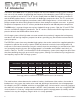
1.0 Introduction The Electro-Voice EVF series is a group of compact two-way front-loaded full-range systems, available with 12- or 15-inch woofers, augmented by low-frequency and subwoofer systems. EVF full-range systems are available in two versions. The “S” versions employ 400-watt SMX low-frequency transducers and the ND2B medium-format, 1.4-inch exit/2-inch diaphragm compression driver. The “D” versions employ 500-watt DVX-A low-frequency transducers and the DH7N large-format, 1.
1.
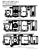
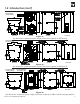
1.0 Introduction (cont’) System Weight 57.7 lb (26.2 kg) End View Front View Side View Rear View Figure 1c: Key dimensions, suspension points, weight, and center-of-gravity for EVF-1121S System Weight 62.6 lb (28.4 kg) End View Front View Side View Rear View Figure 1d: Key dimensions, suspension points, weight, and center-of-gravity for EVF-1151S System Weight 101.2 lb (46.
1.0 Introduction (cont’) System Weight 82.4 lb (37.4 kg) End View Front View Side View Rear View Figure 1f: Key dimensions, suspension points, weight, and center-of-gravity for EVF-2121S System Weight 117.0 lb (53.1 kg) End View Front View Side View Rear View Figure 1g: Key dimensions, suspension points, weight, and center-of-gravity for EVF-2151D “S” System Weight 143.0 lb (64.9 kg) “D” System Weight 145.5 lb (66.
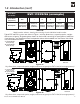
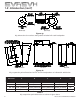
1.0 Introduction (cont’) Washer (x4) Eyebolt (x4) Figure 1g: Key dimensions for washers and eyebolts included with each loudspeaker End View Rear View Side View Figure 1h: Key suspension point dimensions for EVF or EVH loudspeakers as indicated in table below 8 Dimension: A B C D E° EVF 12-inch 4.176” [106.07mm] 14.301” [363.24mm] N/A 16.129” [409.67mm] 15° EVF 15-inch 4.176” [106.07mm] 14.301” [363.24mm] N/A 18.353” [466.16mm] 15° EVF Subs 3.957” [100.50mm] 13.889” [352.
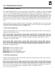
1.0 Introduction (cont’) 1.1 Finishes and Colors Available The standard EVF/EVH indoor versions are finished in tough EVCoat™. In addition, all models are available in two levels of weather resistance, indicated by letters following the coverage-pattern numbers. The FG versions, e.g., EVF-1152S/64-FGB, are designed for full weather exposure and feature a fiberglass-finished enclosure, stainless-steel hydrophobic grille and the CDG dual-gland-nut input-panel cover. The PI versions, e.g.
1.0 Introduction (cont’) 1.4 Accessories for EVF and EVH Systems Note that some accessories are supplied with certain system versions, as noted. CDG: optional dual-gland-nut input-panel cover to protect the input connections from water. Note that this cover is supplied with the weather-resistant versions. CSG: optional single-gland-nut input-panel cover to protect the input connections from water.
3.0 Designing an EVF/EVH Cluster 3.1 General Aiming and Placement Guidelines Loudspeakers should be “pointed at the people” and away from reflective room surfaces. Since people are excellent absorbers of sound and room surfaces are often not, this practice insures not only that the audience will receive the high frequencies necessary for good voice intelligibility and musical clarity but also that the reflective surfaces do not energize the room with intelligibility-robbing reverberation.
3.0 Designing an EVF/EVH Cluster (cont’) 3.3 More on Coverage Patterns, Multiple Coverage Patterns, the Need for Clusters of Loudspeakers and How Far a Single Cluster Can “Reach” into a Venue The coverage patterns or angles mentioned previously are defined where loudspeaker output is 6 dB down from maximum, usually on-axis level.
3.0 Designing an EVF/EVH Cluster (cont’) Figure 2: Typical “reach” of a single loudspeaker into a venue (DI ) in order to maintain the desired ±3 dB coverage is about two times the distance to the closest seats (DS ) Adding a long-throw device will typically extend this reach to about three times the closest distance. See Figure 3.
3.0 Designing an EVF/EVH Cluster (cont’) 3.5 Multiple-Source Interference in Clusters Whenever two or more sources serve a single venue, some seats will receive strong signals from multiple sources. Consider two EVF-1122S/64 60° x 40° systems clustered side by side with their axes 60° apart to form a 120° x 40° cluster. If these systems maintained their rated coverage patterns into the lowfrequency range, there would be essentially no interference.
3.0 Designing an EVF/EVH Cluster (cont’) NORMALIZED This effect is shown in the frequency-response of Figure 5. Given the dimensions of the typical compact loudspeaker systems and when they are clustered in close proximity to one another, the first several interference nulls occur right in the middle of the vocal range. A frequency response with these ever-moreclosely spaced nulls is known as a “comb filter” response, after the visual appearance of the response.
3.0 Designing an EVF/EVH Cluster (cont’) At higher frequencies, the interference patterns become more densely packed, which essentially eliminates their audibility. Figure 7 shows this effect at 8,000 Hz. Figure 7: Horizontal polar response (blue center plot) of two closely clustered 60° x 40° loudspeakers aimed 60° apart, showing multiple, densely packed off-axis nulls at 8,000 Hz caused by multiple-source interference (see text for more details) 3.
3.0 Designing an EVF/EVH Cluster (cont’) One clustering technique that accomplishes this separation without putting a physical space between two full-range systems is putting a low-frequency or subwoofer system between two full-range systems. Such a cluster is shown in Figure 9, assembled with the optional HRK rigging kits. HRK-2 Kit (Sold Separately) HRK-2 Kit (Sold Separately) EVF Full-Range System EVF Subwoofer Note: Loudspeakers are non-specific and shown as an example.
3.0 Designing an EVF/EVH Cluster (cont’) Finally, another way to reduce interference is to apply signal delay of up to 8 milliseconds to one of the two systems. This requires a separate DSP (digital signal processor) drive to the delayed system. Figure 10 shows the dramatic smoothing achieved at 1,250 Hz. Note that the systems are still close together as in Figure 6.
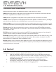
4.0 Preparing EVF and EVH Systems for Installation 4.1 Recommended Preflight Procedures For any installed sound system, certain checks made at the installer’s place of business can prevent expensive on-site delays. A short-list follows, and sets the stage for proper cluster performance: 1. 2. 3. 4. Unpack all loudspeakers in the shop. Check for proper model numbers. Check the overall condition of the loudspeakers. Check for continuity at the loudspeaker inputs.
4.0 Preparing EVF and EVH Systems for Installation (cont’) To configure for biamp operation, remove the switch card by drawing it toward you using the central finger hole. (The switch can also be removed with the end of a flat-blade screwdriver, by placing the blade end in the switch hole and using the adjacent edge of the input panel as a fulcrum. To facilitate this operation, there is a small recess in the edge of the input panel adjacent to the hole in switch card.
4.0 Preparing EVF and EVH Systems for Installation (cont’) Figure 12: An EVH hard foam waveguide contour being removed for reorientation 4.5 Digital Signal Processing 4.51 Full-Range Systems in Passive Mode For full-range systems in the passive mode, the internal crossover/equalizer network sends low frequencies to the woofer and high frequencies to the compression-driver/waveguide combination.
4.0 Preparing EVF and EVH Systems for Installation (cont’) 4.52 Using the EVF-1121S and EVF-1151S Low-Frequency Systems in Full-Range Clusters that Operate on a Single Power-Amplifier Channel The EVF-1121S and EVF-1151S low-frequency systems have integral passive low-pass filters that roll off frequencies above 100 Hz at the rate of 12 dB per octave.
5.0 EVF and EVH Rigging System 5.1 Introduction 5.11 The Flying EV-Innovation (EV-I) Loudspeaker System All EVH and EVF loudspeaker systems incorporate heavy-duty M10-1.5 threaded attachment points on each enclosure. These attachment points work in conjunction with (1) the M10 eyebolts included with each loudspeaker or (2) the optional VRK and HRK rigging kits. The rigging kits allow the user to rig multiple systems together in horizontal and vertical configurations.
5.0 EVF and EVH Rigging System (cont’) M5 Split Lock Washer (x8) EVF Long Rigging Plate (x2) EVF Stabilizing Bar (x2) EVF Short Rigging 3.11 lb Plate (x2) (1.41 kg) 4.87 lb (2.21 kg) 0.88 lb (0.40 kg) M10 Split Lock Washer (x8) M5 Screw (x8) M10 Screw (x8) Figure 14a: VRK-1 rigging kit with parts identified M5 Split Lock Washer (x8) EVF-SUB Long Rigging Plate (x2) EVF-SUB Short 3.25 lb Rigging Plate (x2) (1.48 kg) 5.44 lb (2.47 kg) EVF Stabilizing 0.88 lb (0.
5.0 EVF and EVH Rigging System (cont’) EVF Long Rigging Plate (x2) 7.33 lb (3.33 kg) M10 Split Lock Washer (x8) M10 Screw (x8) EVF Short Rigging Plate (x2) 5.57 lb (2.53 kg) Figure 15a: HRK-1 rigging kit with parts identified EVF-SUB Long Rigging Plate (x2) 7.90 lb (3.59 kg) M10 Split Lock Washer (x8) M10 Screw (x8) EVF-SUB Short Rigging Plate (x2) 5.71 lb (2.59 kg) Figure 15b: HRK-2 rigging kit with parts identified EVH Long Rigging Plate (x2) 9.13 lb (4.
5.0 EVF and EVH Rigging System (cont’) 5.12 Important Details that Apply to the VRK and HRK Rigging Kits Both the VRK and HRK kits include all necessary mounting hardware (as shown in Figures 14 and 15). Additionally, the VRK kits include a set of low-profile stabilizer bars to both simplify alignment of the enclosures during the rigging process and keep the front edges of the systems neatly aligned. Additional hardware is included in the VRK kits to mount these stabilizer bars.
5.0 EVF and EVH Rigging System (cont’) 5.21 Anatomy of an EVF or EVH Flying System Using M10 Eyebolts 5.211 Eyebolt Application Warnings No eyebolt should be mounted in the sides of any EVF or EVH enclosure in order to suspend a system or cluster from the top. Figure 16: Eyebolts installed incorrectly in the sides of an enclosure in order to suspend it from above Eyebolts must be fully seated and oriented in the plane of pull as shown in Figure 17. always use washers to distribute suspension loads.
5.0 EVF and EVH Rigging System (cont’) 5.212 Eyebolt Installation Installation instructions follow: 1. 2. 3. 4. 5. Remove the M10 flat-head bolts from the enclosure (see Figure 18a). Screw the lifting eyebolt with fender washer into the threaded attachment point until the fender washer has contacted the enclosure (see Figure 18b). Continue to finger tighten the eyebolt until the correct alignment position is obtained, a maximum of one complete turn.
5.0 EVF and EVH Rigging System (cont’) 5.213 All-Eyebolt Clusters A basic two-cabinet flying system is shown in Figures 19 and 20, illustrating the components necessary to make a typical two-system horizontal or vertical cluster using M10 eyebolts. Secure cabinets to the building structure with user-supplied hardware. All user-supplied hardware, shackles, wire rope, bolt connectors, etc., must be rated for overhead lifting. Refer to section 1 for suspension point locations.
5.0 EVF and EVH Rigging System (cont’) A horizontal two-cabinet eyebolt hang, shown in Figure 20, is similar to a vertical hang (shown in Figure 19), but with the cabinets rotated and other surfaces used for mounting eyebolts.
5.0 EVF and EVH Rigging System (cont’) 5.22 VRK Kits and Vertically Rigged Clusters A basic three-enclosure vertical hang is shown in Figure 21. The following components are necessary to construct this cluster: 1. 2. 3. One VRK-1 vertical rigging kit for EVF to EVF. One VRK-2 vertical rigging kit for EVF to EVF subwoofer. Four M10 eyebolts from the supplied EVI-M10K eyebolt kit (to suspend the top cabinet).
5.0 EVF and EVH Rigging System (cont’) 5.23 HRK Kits and Horizontally Rigged Clusters The main difference between the HRK and the VRK rigging kits is the addition of a tie plate in the center of the rigging plate. Tie plates are identified in Figure 22. Main suspension lines and pull backs must be tied to the tie plates. Enclosures may be suspended below using the HRK rigging kits. Connection between the enclosures through the tie plates within the HRK kits requires hardware supplied by the end user.
5.
5.
5.0 EVF and EVH Rigging System (cont’) 5.24 Assembly Instructions for VRK and HRK kits Both the VRK and HRK rigging kits share the same mounting hole positions and letter designations. Tables 5, 6, and 7 apply to both the VRK and HRK kits. The only difference between the kits is the HRK rigging plates have an integral tie plate and the VRK kits use a stabilizing bar. 1. Refer to Tables 5, 6, or 7 to determine which lettered hole position to use.
5.0 EVF and EVH Rigging System (cont’) Letter Table 5: For clustering EVF full-range and low-frequency (not subwoofer) systems using VRK-1 or HRK-1 rigging kits A Short in front Toward grille 0° 6.276” [159.41mm] 11.518” [292.56mm] B Short in front Toward grille 5° 5.958” [151.33mm] 10.338” [262.59mm] C Short in front Toward grille 10° 5.630” [143.00mm] 9.144” [232.26mm] D Short in front Toward grille 15° 5.292” [134.42mm] 7.934” [201.52mm] E Long in front Toward input panel 20° 6.
6.0 Rigging-Strength Ratings and Safety Factors 6.1 Working Load Limit and Safety-Factor Definitions The structural ratings for all of the EVF and EVH rigging components and complete loudspeaker systems are based on test results in which parts were stressed to failure. Manufacturers typically present the structural-strength ratings of mechanical components or systems as either the Working Load Limit (WLL) or the ultimate-break strength.
6.0 Rigging-Strength Ratings and Safety Factors (cont’) 6.2 Structural Rating Overview Designing a safe structural cluster is usually a very complex process best left to experienced professionals. Since the EVH and EVF rigging options allow the user to configure a wide variety of clusters, the following guidelines have been broken into three sections: eyebolts, vertical rigging and horizontal rigging. Each section will give the end user guidelines for maximum weight and height of clusters.
6.0 Rigging-Strength Ratings and Safety Factors (cont’) 6.3 All-Eyebolt Structural Ratings The guidelines for simplified all-eyebolt structural ratings cover the following information: 1. 2. 3. 4. 5. Maximum number of enclosures. Maximum weight of the cluster. WLL for eyebolts. Suspension-line angles. Left-to-right all-eyebolt cluster angles. The maximum load, Maximum number of Enclosures and Minimum number of suspension lines for all-eyebolt clusters are listed in Table 8.
6.0 Rigging-Strength Ratings and Safety Factors (cont’) 6.31 Working Load Limits for Eyebolts Eyebolts can be used to suspend individual loudspeakers and certain types of clusters. Eyebolts attach to the EVF and EVH enclosures through the integral M10-1.5 attachment points. Section 5.21 Anatomy of an EVF or EVH Flying System Using M10 Eyebolts should be reviewed at this time for more information on eyebolt alignment and positioning on the enclosure.
6.0 Rigging-Strength Ratings and Safety Factors (cont’) 6.32 Suspension-Line Angles Refer to Table 9 and Figure 25 for specific eyebolt angle and weight limitiations when using all-eyebolt clusters. These limits are not to be exceeded under any circumstances. If a higher safety factor than 8:1 is required, the angle limitations for each eyebolt may actually decrease to a number less than what is shown in Figure 25.
6.0 Rigging-Strength Ratings and Safety Factors (cont’) 6.4 VRK Rigging Structural Ratings for Vertical Clusters The guidelines for simplified vertical structural ratings cover the following information: 1. 2. 3. 4. 5. 6. Maximum length of the cluster. Maximum weight of the cluster. WLL for eyebolts. Trim angle. Tie points for eyebolts. Left-to-right vertical cluster angles. The majority of vertical clusters will be suspended using a combination of VRK vertical rigging kits and factory-supplied eyebolts.
6.0 Rigging-Strength Ratings and Safety Factors (cont’) The maximum load, maximum length and Eyebolt Angle Restrictions for vertical clusters are listed in Table 10. LIMITS FOR VERTICAL CLUSTERS ONLY Maximum Working Load Limit Maximum Length Eyebolt Angle Restrictions 482 lb (219 kg) 7.5 ft (228.6 cm) (as shown in Figure 27) When using eyebolts, refer to Table 12 and Figure 29 for angle restrictions.
6.0 Rigging-Strength Ratings and Safety Factors (cont’) 6.41 Working Load Limits for Eyebolts used with VRK Vertical Rigging Kits Eyebolts are the most convenient way to suspend vertical clusters. Eyebolts attach to the EVF and EVH enclosures through the integral M10-1.5 attachment points. Section 5.21 Anatomy of an EVF or EVH Flying System Using M10 Eyebolts should be reviewed at this time for more information on eyebolt alignment and positioning on the enclosure.
6.0 Rigging-Strength Ratings and Safety Factors (cont’) 6.42 Left-to-Right Vertical Cluster Angles The suspended vertical cluster must be perpendicular (plumb) to within ±5° as shown in Figure 30.
6.0 Rigging-Strength Ratings and Safety Factors (cont’) 6.5 HRK Rigging Structural Ratings for Horizontal Clusters The guidelines for simplified horizontal structural ratings cover the following information: 1. 2. 3. 4. 5. 6. 7. 8. Maximum height of the cluster. Maximum weight of the cluster. Cluster combinations, per weight and height. Using tie plates for suspension. Suspension-line angles for HRK rigging. Symmetry of cluster. Inner connection points. Left-to-right horizontal cluster angles.
6.0 Rigging-Strength Ratings and Safety Factors (cont’) 6.51 Using Tie Plates as Main Load-Bearing Suspension Horizontal clusters are attached to the structure with the tie plates located on the rigging plates of the HRK kits. The tie plates have six holes that will accept a 5/8-inch shackle or similar connector. All main suspension lines that carry the cluster’s load should be tied to these tie plates.
6.0 Rigging-Strength Ratings and Safety Factors (cont’) 6.52 Suspension-Line Angles for HRK Kits Suspension-line angles are restricted to 30° off the axis of the tie plate’s center line. Figure 32 shows the angle limitations recommended for horizontal clusters when using HRK kits.
6.0 Rigging-Strength Ratings and Safety Factors (cont’) 6.53 Symmetry for Horizontal Clusters using HRK Kits The cluster’s center of gravity is centered under the two suspension points in a two-over-two cluster (see Figure 33a) or between the suspension points in a three-over-three cluster (see Figure 33b). Both the cluster’s weight and center of gravity must be symmetrical about the cluster’s center line. For individual enclosure weights and centers of gravity, refer to section 1.
6.0 Rigging-Strength Ratings and Safety Factors (cont’) 6.54 Inner Connection Points For connection between the clusters (from bottom of top enclosure to the top of the bottom enclosure), both the front and rear rigging plates must be connected (see Figure 34). The maximum box-to-box angle is 45°. When Rigging Box-to-Box, both front and rear tie plates must be connected. Figure 34: Box-to-Box internal connection points of a horizontal cluster using HRK horizontal rigging kits 6.
6.0 Rigging-Strength Ratings and Safety Factors (cont’) 6.6 Ratings for Outdoor Applications with Wind Loading Special considerations must be made for outdoor venues where wind conditions could become a concern. High wind gusts can push the loudspeakers in a way that the suspension lines’ direction of force can become misaligned with the plane of the eyebolt. Larger clusters pose more of a concern because more surface area exists for the wind to act upon.
7.0 Rigging Inspections and Precautions Electro-Voice EVF and EVH Loudspeaker Systems: Prior to each use, inspect the enclosures for any cracks, deformations or missing or damaged components that could reduce enclosure strength. Inspect the rigging plates, tie plates and stabilizer bars between enclosures for cracks, corrosion or other deformations that could reduce their strength and integrity.
8.0 References 8.1 Rigging (printed) [1] W.E. Rossnagel, L.R. Higgins & J.A. MacDonald, Handbook of Rigging for Construction and Industrial Operations, McGraw-Hill Book Company, New York, NY, USA (1988). [2] H. Donovan, Entertainment Rigging, http://www.riggingbooksandprograms.com, Rigging Seminars, Seattle, WA, USA (2002) [3] J.O. Glerum, Stage Rigging Handbook, Southern Illinois University Press, Carbondale, IL, USA (1987). [4] P. Carter, Backstage Handbook, Broadway Press, New York, NY, USA (1988).
Notes 54 Electro-Voice EVF/EVH User Manual
Notes Electro-Voice EVF/EVH User Manual 55
Electro-Voice® 12000 Portland Avenue South, Burnsville, MN 55337 Phone: 952/884-4051, Fax: 952/884-0043 www.electrovoice.com © Bosch Communications Systems Part Number LIT000282 Rev E 08/2010 U.S.A. and Canada only. For customer orders, contact Customer Service at: 800/392-3497 Fax: 800/955-6831 Europe, Africa, and Middle East only. For customer orders, contact Customer Service at: + 49 9421-706 0 Fax: + 49 9421-706 265 Other Internatonal locations.