OWNER’S MANUAL BEDIENUNGSANLEITUNG CHANNEL 1 CHANNEL 1 CHANNEL 2 CHANNEL 2 CHANNEL 3 CHANNEL 3 CHANNEL 4 CHANNEL 4 CHANNEL 5 VOLUME CHANNEL 6 PWS PROGRAMMABLE WALL STATION
PROGRAMMABLE WALL STATION 2 CONTENTS Introduction . . . . . . . . . . . . . . . . . . . . . . . . . . . . . . . . . . . . . . . . . . . . . . . . . . . . . . . . . . . . . . . . . Overview . . . . . . . . . . . . . . . . . . . . . . . . . . . . . . . . . . . . . . . . . . . . . . . . . . . . . . . . . . . . . . Applications . . . . . . . . . . . . . . . . . . . . . . . . . . . . . . . . . . . . . . . . . . . . . . . . . . . . . . . . . . . . IRIS-Net™ . . . . . . . . . . . . . . . . . . . . . . . . . . .
PROGRAMMABLE WALL STATION IMPORTANT SAFETY INSTRUCTIONS The lightning flash with arrowhead symbol, within an equilateral triangle is intended to alert the user to the presence of uninsulated “dangerous voltage“ within the product’s enclosure that may be of sufficent magnitude to constitute a risk of electric shock to persons.
PROGRAMMABLE WALL STATION 1 Introduction 1.1 Overview The programmable wall stations of the modular PWS system (Programmable Wall Station) allow local control and operation of various devices and systems via CAN-Bus. A programmable wall station lets you control several functions, for example: source selection, volume control, muting or powering on/off devices. In addition, using a suitable central control unit allows controlling a variety of facilities in a building (light, heating/air condition, etc.).
PROGRAMMABLE WALL STATION 1.2 Applications PWS panels can be included in any audio installation, for example: • Stadiums and theaters • Cruise ships • Multi-purpose halls • Schools and Universities • Government agencies • Airports • Theme parks • Exhibition centers and museums • Conference centers and hotels 1.3 IRIS-Net™ When shipped, programmable wall stations have not been configured yet.
PROGRAMMABLE WALL STATION 2 CAN-Bus coupler PWS-C The CAN-Bus coupler PWS-C provides connection between front units (e.g. PWS-4) and the CAN-Bus. The CAN-Bus coupler registers the activation of controls on the connected front units and sends the needed information via CAN-Bus to the devices to be controlled, but also directs information received from the CAN-Bus to the control units for indication.
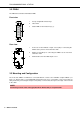
PROGRAMMABLE WALL STATION 3 PWS Front Unit PWS-4/PWS-6 PWS-4 and PWS-6 are front units of the modular PWS system. They are meant for installation in a UStype wall box. Typical applications are: source selection, volume control and preset-switching. All controls and indicators of the front units are freely configurable via IRIS-Net™. Individually labeling the controls and indicators according to their assign functions is possible after removing the label field cover.
PROGRAMMABLE WALL STATION 3.2 PWS-6 The PWS-6 has 6 buttons with Status-LEDs.
PROGRAMMABLE WALL STATION Only the supplied connection cables should be used for proper operation. The following illustration shows the connection of two front units of a programmable wall station. Abbildung 3.1: Connecting two front units of a programmable wall station Other than connections, no physical configuration of the front units is required, as the assignment of functions and other configurations are performed in IRIS-Net™.
PROGRAMMABLE WALL STATION 4 Initial Operation When shipped, PWS panels have not been configured yet. The following illustration provides an overview of the entire procedure of installing and configuring a PWS for the first time. Please also refer to the descriptions of other connected devices in the corresponding chapters as well as the IRIS-Net™ on-line help feature. Screw CAN-Bus coupler and a front unit together, connect additional front units See chapter PWS-C, PWS-4, etc.
PROGRAMMABLE WALL STATION Mounting a Programmable wall station in a US Single Gang Wall Box For mounting a programmable wall station you have to lock the PWS-C and a front unit of a programmable wall station together using two screws. Using the supplied connection cables, connect additional front units. Please also refer to this manual’s corresponding chapters describing the connection procedure for the front units being used. USE SPACERS IF NO PWS-C IS USED 4.
PROGRAMMABLE WALL STATION Baud rate (in kbit/s) Bus-length (in m) 500 100 250 250 125 500 62,5 1000 20 2500 10 5000 Table 4.1: Baud rate and Bus-length in CAN-networks Setting the Baud Rate Setting the bus coupler’s baud rate is possible by using switches 1, 2 and 3 of the TERM/BAUD DIP-switches. Potential baud rates and corresponding switch settings are shown in the following table. Only when set to PROG Mode, it is possible to change the programmable wall station’s baud rate via IRIS-Net™.
PROGRAMMABLE WALL STATION Setting a default baud rate in PROG mode As shown in the above table, setting a fixed baud rate is possible when connecting a PWS-C to an already existing CAN-Bus. When connecting a PWS-C in PROG mode, setting the baud rate directly on the PWSC is possible by following these instructions: 1. Activate the power supply of the PWS-C 2. Set the desired baud rate using the DIP-switch TERM/BAUD (see page 12) 3.
PROGRAMMABLE WALL STATION CAN address CAUTION: To prevent network faults, each CAN address may exist once only throughout a system. Conflicts on the network would be the result. Every programmable wall station has to have a unique CAN address to be identified on the CAN-Bus. The usable address range is: 1 (01 hex) up to 250 (FA hex). The PWS-C’s ADDRESS DIP switch (see page 6) allows specifying the CAN address by setting a two-digit hexadecimal number.
PROGRAMMABLE WALL STATION 4.2 CAN-Status-LED The entries in following table are arranged after falling priority, i.e. if two conditions arise at the same time, only the upper condition in the table is indicated.
PROGRAMMABLE WALL STATION Connecting the CAN-Bus Comprehensive guidelines regarding cabling and bus length are provided in chapter “CAN-Bus Principles” starting on page 19. Supply Voltage Programmable wall stations need to be operated on a power source that delivers a direct-current voltage between 9 volts and 58 volts. A central power supply unit or local power sources can be used if various wall panels are operated on a single CAN-Bus.
PROGRAMMABLE WALL STATION 4.4 Find Function The Find Function simplifies identifying a programmable wall station when a variety of (identical) wall stations are operated on the same CAN-Bus. When the Find Function is active, the CAN-STATUS-LED on the PWS-C’s rear blinks (and, if existing, the LEDs of the front unit selected in IRIS-Net™) as shown in the table on page 15. The LEDs of all other wall stations for which the Find Function has not been activated do not light.
PROGRAMMABLE WALL STATION Diagnostic mode is automatically cancelled under following conditions: • Either no button on the front unit has been pressed for at least 15 seconds • or the CAN-Bus is operational again • or unlocking the diagnostic mode has been deactivated in IRIS-Net™. 4.
PROGRAMMABLE WALL STATION 5 CAN-Bus Principles The network topology used by the CAN bus is based on the so-called “bus or line topology”, i.e. all participants are connected via a single two-wire cable (Twisted-Pair cable, shielded or unshielded) with the cabling running from one participant on the bus to the next, allowing unlimited communication among all devices. In general, it does not matter if the bus member is a power amplifier, a N8000 or a UCC1 USBCAN converter.
PROGRAMMABLE WALL STATION CAN-Bus Cabling Specifications According to the ISO 11898-2 standard, CAN-bus data transfer cabling has to be carried out using TwistedPair cables with or without shielding providing a characteristic impedance of 120 Ω. Both ends of a CANbus need to be terminated with 120 Ω termination-plugs. The maximum bus-length depends on the actual data transfer rate, the kind of data transfer cable being used, as well as the total number of participants on the bus.
BEDIENUNGSANLEITUNG CHANNEL 1 CHANNEL 1 CHANNEL 2 CHANNEL 2 CHANNEL 3 CHANNEL 3 CHANNEL 4 CHANNEL 4 CHANNEL 5 VOLUME CHANNEL 6 PWS PROGRAMMABLE WALL STATION
PROGRAMMABLE WALL STATION WICHTIGE SICHERHEITSHINWEISE Das Blitzsymbol innerhalb eines gleichseitigen Dreiecks soll den Anwender auf nicht isolierte Leitungen und Kontakte im Geräteinneren hinweisen, an denen hohe Spannungen anliegen, die im Fall einer Berührung zu lebensgefährlichen Stromschlägen führen können. Das Ausrufezeichen innerhalb eines gleichseitigen Dreiecks soll den Anwender auf wichtige Bedienungs- sowie Servicehinweise in der zum Gerät gehörenden Literatur aufmerksam machen. 1. 2. 3. 4. 5. 6.
PROGRAMMABLE WALL STATION 1 Einführung 1.1 Überblick Die Wand-Bedienpanels des modularen PWS-Systems (Programmable Wall Station) ermöglichen die lokale Bedienung und Steuerung verschiedener Geräte und Systeme über den CAN-Bus. Über ein WandBedienpanel können verschiedenste Funktionen, zum Beispiel Quellenwahl, Lautstärkeregelung, Stummschaltung oder Ein-/Ausschalten von Geräten ausgeführt werden.
PROGRAMMABLE WALL STATION 1.2 Anwendungsmöglichkeiten Anwendungsmöglichkeiten für PWS-Wand-Bedienpanels sind alle Arten von Audio-Installationen, z.B. • Stadien und Theater • Kreuzfahrtschiffe • Mehrzweckhallen • Schulen und Universitäten • Behörden • Flughäfen • Freizeitparks • Ausstellungsräume und Museen • Konferenzzentren und Hotels 1.3 IRIS-Net™ Ab Werk werden Wand-Bedienpanels ohne Konfiguration ausgeliefert, für die Zuweisung der Bedien- bzw.
PROGRAMMABLE WALL STATION 2 CAN-Bus-Koppler PWS-C Der CAN-Bus-Koppler PWS-C stellt die Verbindung zwischen den Frontbedieneinheiten (z. B. PWS-4) und dem CAN-Bus her. Hierbei erfasst der CAN-Bus-Koppler einerseits die Betätigung von Schaltelementen auf den angeschlossenen Bedieneinheiten und sendet Informationen über den CAN-Bus an zu steuernde Geräte. Andererseits werden vom CAN-Bus empfangene Informationen auf den Bedieneinheiten angezeigt.
PROGRAMMABLE WALL STATION 3 PWS-Frontbedieneinheiten PWS-4/PWS-6 PWS-4 und PWS-6 sind Frontbedieneinheiten des modularen PWS-Systems. Sie sind für den Einbau in eine US Wallbox vorgesehen. Typische Anwendungsmöglichkeiten sind Quellenauswahl, Lautstärkeregelung und Preset-Umschaltung. Alle Bedien- und Anzeigeelemente der Frontbedieneinheiten sind über IRIS-Net™ frei konfigurierbar.
PROGRAMMABLE WALL STATION 3.2 PWS-6 Das PWS-6 besitzt 6 Tasten mit Status-LED. Frontseite: 2 CHANNEL 1 1 Frei konfigurierbare Funktionstasten 2 Beschriftungsfeld 3 Status-LEDs für Funktionstasten (1) 1 Anschluss für PWS-C bzw.
PROGRAMMABLE WALL STATION Um Verdrahtungsfehler zu vermeiden sollten ausschließlich die mitgelieferten Verbindungskabel verwendet werden. Folgende Abbildung zeigt die Verbindung von zwei Frontbedieneinheiten eines WandBedienpanels. Abbildung 3.1: Verbindung von zwei Frontbedieneinheiten eines Wand-Bedienpanels An den Frontbedieneinheiten muss keinerlei Hardware-Konfiguration vorgenommen werden. Die Zuweisung von Funktionen erfolgt vollständig über IRIS-Net™.
PROGRAMMABLE WALL STATION 4 Inbetriebnahme PWS-Wand-Bedienpanels werden unkonfiguriert ausgeliefert. Folgende Abbildung zeigt den gesamten Ablauf der Inbetriebnahme eines PWS-Systems im Überblick. Bitte beachten Sie die Kapitel der verwendeten Geräte und die Online-Hilfe von IRIS-Net™. CAN-Bus-Koppler mit einer Frontbedieneinheit verschrauben, weitere Frontbedieneinheiten verbinden Siehe Kapitel PWS-C, PWS-4 usw.
PROGRAMMABLE WALL STATION Montage eines Wand-Bedienpanels in eine US Single Gang Wall Box Für den Einbau des Wand-Bedienpanel wird der PWS-C mittels zweier Schrauben mit einer Frontbedieneinheit des Wand-Bedienpanels verbunden. Weitere Frontbedieneinheiten werden mit den im Lieferumfang enthaltenen Verbindungskabeln verbunden, beachten Sie hierzu die Hinweise in den Kapiteln der verwendeten Frontbedieneinheiten in diesem Dokument. USE SPACERS IF NO PWS-C IS USED 4.
PROGRAMMABLE WALL STATION Baudrate (in kbit/s) Buslänge (in m) 500 100 250 250 125 500 62,5 1000 20 2500 10 5000 Tabelle 4.1: Baudrate und Buslänge in CAN-Netzwerken Einstellung der Baudrate Zur Einstellung der Baudrate des Bus-Kopplers werden die Kontakte 1, 2 und 3 von DIP-Schalter TERM/BAUD verwendet. Die möglichen Baudraten und zugehörigen Schalterstellungen sind in folgender Tabelle angegeben.
PROGRAMMABLE WALL STATION Voreinstellung einer Baudrate im PROG-Modus Beim Anschluss eines PWS-C an einen bestehenden CAN-Bus kann wie in obenstehender Tabelle angegeben die Baudrate fest eingestellt werden. Soll das PWS-C im PROG-Modus angeschlossen werden, kann die Baudrate mit folgenden Schritten direkt am PWS-C voreingestellt werden. 1. Spannungsversorgung des PWS-C aktivieren 2. Einstellung der gewünschten Baudrate an DIP-Schalter TERM/BAUD (siehe Seite 31) 3.
PROGRAMMABLE WALL STATION CAN-Adresse ACHTUNG: Jede CAN-Adresse darf im System nur einmal vorkommen, da es sonst zu NetzwerkKonflikten kommt. Jedes Wand-Bedienpanel benötigt eine eindeutige CAN-Adresse zur Identifikation am CAN-Bus. Es können die Adressen 1 (01 hex) bis 250 (FA hex) verwendet werden. Mit DIP-Schalter ADDRESS des PWS-C (siehe Seite 25) wird die CAN-Adresse als zweistellige Zahl im hexadezimalen Zahlensysteme eingestellt.
PROGRAMMABLE WALL STATION 4.2 CAN-Status-LED Folgende Tabelle zeigt die verschiedenen Anzeigemöglichkeiten der CAN-Status-LED. Die Einträge sind nach fallender Priorität angeordnet, d.h. treten zwei Zustände gleichzeitig auf, wird nur der in der Tabelle weiter oben stehende Zustand signalisiert.
PROGRAMMABLE WALL STATION Anschluss des CAN-Busses Ausführliche Richtlinien zur Verdrahtung und Buslänge sind im Abschnitt CAN-Bus-Grundlagen ab Seite 38 zu finden. Versorgungsspannung Zur Spannungsversorgung des Wand-Bedienpanels kann eine Gleichspannung im Bereich 9 Volt bis 58 Volt verwendet werden. Werden mehrere Wand-Bedienpanels an einem CAN-Bus betrieben, kann die Spannungsversorgung entweder über ein zentrales Netzteil oder lokal erfolgen.
PROGRAMMABLE WALL STATION 4.4 Find-Funktion Die Find-Funktion erleichtert die Identifkation eines Wand-Bedienpanels bei Verwendung mehrerer (gleichartiger) Wand-Bedienpanels an einem CAN-Bus. Bei aktivierter Find-Funktion blinkt die rückseitige CAN-STATUS-LED auf dem PWS-C (und, falls vorhanden, die LEDs einer in IRIS-Net™ ausgewählten Frontbedieneinheit) wie in der Tabelle auf Seite 34 angegeben.
PROGRAMMABLE WALL STATION 2. Verwenden Sie die 4 obersten Tasten dieser Frontbedieneinheit zur Abfrage der gewünschten Parameter. Die im Diagnosemodus abfragbaren Parameter sind in Tabelle 4.5 aufgeführt Der Diagnosemodus wird unter folgenden Bedingungen automatisch verlassen: • Entweder wurde mindestens 15 Sekunden lang keine Taste an der Frontbedieneinheit betätigt • oder der CAN-Bus ist wieder in Betrieb • oder die Freischaltung des Diagnose-Modus wurde in IRIS-Net™ deaktiviert. 4.
PROGRAMMABLE WALL STATION 5 CAN-Bus-Grundlagen Der CAN-Bus verwendet als Netzwerktopologie die so genannte „Bus- oder Linien-Topologie“. Das heißt, alle Teilnehmer sind an einer einzigen Zweidrahtleitung (Twisted-Pair-Kabel, geschirmt oder ungeschirmt) angeschlossen, wobei die Verkabelung von einem Busteilnehmer zum nächsten verlaufen muss. Jedes Gerät kann hierbei uneingeschränkt mit jedem anderen Gerät kommunizieren.
PROGRAMMABLE WALL STATION • Bildung alternativer Netztopologien Durch die Verwendung von einem oder mehreren Repeatern ist neben der oben dargestellten BusTopologie auch der Aufbau anderer Netztopologien möglich. Leitungsspezifikation Gemäß dem ISO 11898-2 Standard sollten für den CAN-Bus als Datenübertragungskabel vorzugsweise Twisted-Pair-Leitungen, geschirmt oder ungeschirmt, mit einem Wellenwiderstand von 120 Ω zum Einsatz kommen.
PROGRAMMABLE WALL STATION Grundsätzlich gilt: 40 • Für die Rack-Verdrahtung können handelsübliche RJ-45 Patchkabel mit 100 Ω Wellenwiderstand verwendet werden (AWG 24 / AWG 26), wenn es sich nur um kurze Strecken handelt (bis zu 10 Meter). • Für die Verdrahtung der Racks untereinander und in der Gebäudeinstallation sind unbedingt die oben genannten Richtlinien für die Netzwerkverkabelung einzuhalten.
PROGRAMMABLE WALL STATION 6 Specification PWS-C PWS-C GENERAL SPECIFICATIONS Supply Voltage Range 9...58 V DC Supply Current 20 mA @ 24 V DC Power Consumption 480 mW Operating Temperature Range -5 °C...+40 °C Max. Line Length (CAN bus) 1000 m Cable diameter (solid wire) 0.5 - 0.8 mm / 20 - 24 AWG Dimensions (W x H x D) 48 x 48.5 x 19 mm Weight 15 g PWS-4 / PWS-6 PWS-4 PWS-6 Supply Voltage (via PWS-C) Supply Current (via PWS-C) Max.
PROGRAMMABLE WALL STATION 6.1 Block Diagram PWS-C S RAM FLASH EEP RO M RES ET M IC R O C O N TR O LLER B audrate , Term ination W ATC H DO G +5V C AN A ddress S tatus LED Yellow DC Undervoltage detect t 1 DC +5V R esetable fuse 2 3 4 5 VC C CA N L CA N H 1 CAN 2 Up to 3 PW S-X G ND +5V 3 G ND VC C GND 4 5 6.2 Dimensions PWS-C 1.91” (48.5mm) 42 1.89” 0.
PROGRAMMABLE WALL STATION PWS-4 PWS-6 43
PROGRAMMABLE WALL STATION 6.
PROGRAMMABLE WALL STATION 6.
PROGRAMMABLE WALL STATION 46
PROGRAMMABLE WALL STATION Notes Bedienungsanleitung 47
PROGRAMMABLE WALL STATION Americas Asia & Pacific Rim Telex Communications Inc. 12000 Portland Ave South, Burnsville, MN 55337, USA USA: Japan: EVI Audio Japan Ltd. 5-3-8 Funabashi Setagaya-Ku Tokyo Japan 156-0055 Phone: +81 3-5316-5020 Fax: +81 3-5316-5031 China: Telex EVI Audio (Shanghai) Ltd. Room 3105-3109 No. 1 Building No.