DOUBLE COOKTOP WITH SAFETY 073700732 Instructions for installation and use UK
For your safety The use of this new appliance is east. Nevertheless it is important to read carefully this handbook before installing and using the appliance for the first time. In this way you can obtain the best performance, avoid wrong behaving, using the appliance in absolute safety and respect the environment. Installation The installation of the appliance and the connection to the electricity supply has to be carried out by QUALIFIED PERSONNEL ONLY.
Index For the user For your safety Use instructions Cleaning and maintenance Periodical maintenance Assistence and spareparts Guarantee conditions For the instraller 2 4 5 5 6 6 Technical features Installer instructions Connection to the gas supply Connection to the electricity supply Adjustment to the different types of gas Adjustment to the different types of gas Guide to the instructions reading These symbols will help you in finding quickly the most important information.
Use instructions Before using the appliance, remove all the packing materials, advertising labels included and eventual protective film. The control knobs of the cooker top On the front side of the top you will see the knobs for the gas burners’ running/working. The symbols indicated on the knobs have the following meaning: No gas supply (knob turned off) Maximum gas supply Minimum gas supply Burners ignition To obtain the flame easily, turn the burner on before putting saucepan on the grid.
Cleaning and maintenance Before any intervention it is necessary to control the appliance is UNCONNECTED from the electricity supply. General cleaning Wash the enamelled parts with warm water and detergent, avoiding to use abrasive products which could scratch it. Wash often the crowns and the grid caps with boiling soapy water, pay attention to scrape every scale off. After the use rinse the stainless steel parts carefully using water, and dry them with a soft cloth.
Assistance and spare parts. This appliance, before leaving the warehouse, has been tested and set by qualified personnel to obtain the best working performance. If any repairs are required, they have to be done with the maximum care and attention. For this reason we recommend you to contact the retailer who dealt with the sale or the closest Assistance Centre, specifying the type of inconvenience, the appliance model (Mod.), the product number (Prod. No.) and the manufacturing number (Ser. No.).
Technical features Gas burners power Ultra-rapid treble crown burner (big) Rapid burner (big) Auxiliary burner (small) Semi-rapid burner (medium) Category 4,0 Kw 3,0 Kw 1,0 kW 2,0 kW Appliance Calibration Gas inlet connector Feeling tension Methane Gas 20 mbar G 1/2" 230 V 50 Hz Dimensions for the recess opening II2H3+ Width Depth 264 mm 531 mm Instructions for the installer WARNING: This appliance can be installed and can work only in permanently well-ventilated rooms in accordance with o UNI 7129
Discharge of flue gases Connection to the gas-supply. Cooking appliances must always discharge the flue gases into special hoods, which must be connected to chimneys or have direct access to the outside.(picture7). If it is not possible to install a hood, it is necessary the employment of an electric fan fitted to the external wall or to the window, as long as there are the conditions for the increase of the ventilation (see picture 8), reported to the power of the fan itself. (UNI-CIG7129).
Electrical connection The appliance is set up for a single-phase 230V feeling voltage. The connection has to be carried out in compliance with the current directives and law dispositions.
Replacing the electrical power cable If necessary the electrical power must be replaced exclusively with power cables type H05V2V2-F T90 suitable for the load and temperature rating. It is also important that the earth wire (Yellow/Green) must be at least 2 cm longer than the other phase neutral (picture 11)- (picture 12). After the connection test the heating elements letting them work bout 3 minutes. Fig.
Adjustment to different types of gas Replacing the nozzles 1. Remove the grids. 2. Remove the grid caps and burnes’ crowns. 3. With a 7 socket spanner unscrew and take out the nozzles (picture 13), substitute them with those corresponding to the working gas type (see table next page). 4. Reassemble the parts/elements by executing the above described operations in the opposite direction. 5. Substitute the calibration rating plate (positioned near the feed ear).
BY-PASS DIAMETRES Burner Ø By-pass tap in hundredth Auxiliary 28 Semi-rapid 32 Rapid 40 Ultra-rapid with treble crown 56 BURNERS SPECIFICATIONS TYPE OF GAS NATURAL GAS (Methane) LIQUID GAS (Butane/ Propane) 12 TYPE OF BURNER NOZZLES MARKING 1/100 mm NOMINAL THERMIC RATE kW REDUCED TERMIC RATE kW NOMINAL IN RATE m3 /h g/h Ultra-rapid (big) 146 4,0 1,2 0,381 - Rapid 119 3,0 0,65 0,305 - Semi-rapid (medium) 96 2,0 0,45 0,190 - Auxiliary (small) 70 1,0 0,33 0,095 - U
Cooktops typologies Double cooks with castiron grids Double Cooktop Rapid – Semi-rapid Double Cooktop Treble Crown - Auxiliary 13
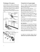
Positioning and connection Cookers can be mounted on a furniture with a recess opening with dimensions shown in picture16 The fixing of the hob to the top has to be done as follows: Position the suitable dope, not issued, on the front, back and side edges of the worktop’s opening (as shown in picture. 16). Ad just the hob on the opening of the furniture paying attention to centre it. Fix the hob to the furniture using provided brackets (see picture 19).
The symbol on the product, or on the documents accompanying the product, indicates that this appliance may not be treated as household waste. Instead it shall be handed over to the applicable collection point for the recycling of electrical and electronic equipment. Disposal must be carried out in accordance with local environmental regulations for waste disposal.