Installation Instructions Electrolux Front-Load Washer Instrucciones de Instalacion Lavadora de carga frontal Electrolux Instructions d’installation Laveuse à chargement frontal Electrolux 137064300 A (0801)
Finding Information Please read and save this guide Thank you for choosing Electrolux, the new premium brand in home appliances. These Installation Instructions are part of our commitment to customer satisfaction and product quality throughout the life of your new appliance. We view your purchase as the beginning of a relationship. To ensure our ability to continue serving you, please use this page to record important product information.
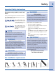
Safety Important Safety Instructions WARNING Recognize safety symbols, words and labels FIRE HAZARD For your safety the information in this manual must be followed to minimize the risk of fire or explosion or to prevent property damage, personal injury or loss of life. Do not store or use gasoline or other flammable vapors and liquids in the vicinity of this or any other appliance.
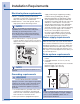
Installation Requirements Electrical system requirements CIRCUIT - Individual, properly polarized and grounded 15 amp. branch circuit fused with 15 amp. time delay fuse or circuit breaker. POWER SUPPLY - 2 wire, with ground, 120 volt single phase, 60 Hz, Alternating Current.
Installation Requirements Clearance requirements IMPORTANT MINIMUM INSTALLATION CLEARANCES - Inches (cm) DO NOT INSTALL YOUR WASHER: 1. In an area exposed to dripping water or outside weather conditions. The ambient temperature should never be below 60° F (15.6° C) to maximize detergent effectiveness. 2. In an area (garage or garage-type building) where gasoline or other flammables (including automobiles) are kept or stored. 3. On carpet. Floor MUST be solid with a maximum slope of 1 inch (2.54 cm).
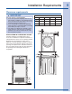
Installation Requirements Installed washer dimensions 50.6” (128.53cm)* to clear open door 27.00” (68.58cm) 31.50” (80.01cm)* to front of closed door water supply connection on rear of unit ¹ power cord on rear of unit ³ drain hose on rear of unit ² 38.00” (96.52cm) freestand washer on floor floor line 53.00” (134.62cm) washer mounted on optional pedestal floor line * To obtain these minimal depth dimensions, dryer must either be vented straight back or with a quick-turn 90° elbow.
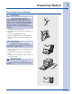
Unpacking Washer Removing foam packaging WARNING SUFFOCATION HAZARD Destroy the carton and plastic bags after the washer is unpacked. Children might use them for play. Cartons covered with rugs, bedspreads, or plastic sheets can become airtight chambers causing suffocation. Place all materials in a garbage container or make materials inaccessible to children. 1. Temporarily remove door tape. 2. Open washer door and remove everything from the drum. 3. Close door and reapply door tape. 4.
Unpacking Washer Removing shipping hardware 1 SHIPPING FORK 5 P CLAMPS 5 SPACERS 5 BOLTS NOTE Rubber expansion material on spacers may need time to relax before they can be easily pulled through shipping hole. UNIVERSAL WRENCH (SUPPLIED) Remove all of the following: 1 SHIPPING FORK 5 P CLAMPS 5 SPACERS 5 BOLTS IMPORTANT Save all shipping bolts and spacers for future use. If the washer is to be transported at a later date, the shipping hardware must be reinstalled to help prevent shipping damage.
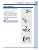
Installation Instructions Leveling your washer Excessive noise and vibration can be prevented by properly leveling the washer. 1. For free standing installation and with the washer within 4 feet (1 m) of its final location, place a level on top of the washer. 2. Use the universal wrench to adjust the leveling legs so the washer is level front-to-rear and side-to-side, and stable corner-to-corner. 3. Press down on alternate corners and sides and feel for the slightest movement.
Installation Instructions Connecting inlet water 1. Run some water from the hot and cold faucets to flush the water lines and remove particles that might clog the water valve screens and to determine which faucet is hot and which is cold supply. 2. Look in the end of each water supply inlet hose and verify that the rubber washers are in place. RUBBER WASHERS MUST BE PRESENT NOTE HOT and COLD water inlet hoses are color coded for identification.
Installation Instructions Connecting drain and electrical 1. Snap one end of the drain hose hanger (shipped in washer drum) onto the drain hose. Continue wrapping it around the hanger and snap it in place. 2. Place the hook end of the drain hose in the drain opening. Secure the drain hose with the cable tie (provided in the enclosure package) to the standpipe, inlet hose, laundry tub, etc. so the hose does not pull out from the force of the water.
Installation Instructions Performing Installation Cycle If your washer has this console: 1. Empty washer’s drum and close door. 2. After you plug in the washer the first time: wake up the washer by pressing any button, rotate cycle knob to hand wash cycle, press the start button and then the cancel button. 3. Wake up the washer again by pressing any button, then immediately and simultaneously press and hold both the eco friendly and my favorite buttons for 5 seconds, or until the LCD display changes.
Reversing Door Preparing to reverse door swing 1 Be sure you have adequate swing area before reversing door. Tools needed: 2 You will need a screw driver with a #2 square bit. 3 Protect flat work surface, such as top of washer or floor near washer, with a soft cloth or towel. 4 Be sure washer is unplugged from power source! Screwdrivers with #2 square & straight bit WARNING ELECTRICAL SHOCK HAZARD Failure to disconnect power source before servicing could result in personal injury or even death.
Reversing Door C) Removing Hinge from Front Panel 1 With the hinge in open position, remove 2 short, course-thread, panhead screws on hinge plate. D) Removing Door Lock from Front Panel 1 Remove 2 short, course-thread, panhead screws from the door lock. 2 Slide the lock toward the outer edge of the front panel. Pivot the lock slightly outward while slowly pulling it through opening to expose the attached harness. 2 Remove 3 short, fine-thread, counter-sunk screws in hinge side.
Reversing Door Reversing door and hardware E) Reattaching Door Lock to Front Panel F) Reattaching Hinge to Front Panel 1 Rotate the door lock and move it to the opposite opening. 1 Rotate the hinge and move it to the opposite opening. 2 Connect the harness to the door lock by inserting it in the terminal and firmly pushing it in place. 2 Connect the harness to the hinge retainer by inserting it in the retention terminal and gently pushing until you hear the fastening tab click.
Reversing Door G) Removing Striker Plate I) Removing Hole Plug 1 Remove 2 long, course-thread, counter-sunk screws and striker plate. 2 Set the striker plate to the side for later. H) Removing Latch Indicator 1 Insert flat blade screwdriver into open slot of hole plug. 2 Gently pry upward to release tab. 3 Pull the hole plug out and set it aside. 1 Insert flat blade screwdriver into open slot of latch indicator. 2 Gently pry upward to release tab. 3 Pull the indicator out and set it aside.
Reversing Door J) Reinserting Latch Indicator 1 Rotate the latch indicator and move it to the opposite hole in the door. K) Reattaching Striker Plate 1 Rotate the striker plate and move it to the opposite side of door above the indicator. 2 Reattach with 2 long, course-thread, counter-sunk screws. insert indicator through slot 2 Firmly insert the two small tabs on either side of the latch indicator into the two slots on either side of the hole in the door.
Reversing Door Reattaching door and hardware M) Reattaching Door Assembly O) Reinstalling Trim Ring 1 Open the hinge to a 90 degree angle. 1 Close the door. 2 Install the door onto the hinge locating pins. 2 Orient the trim so 12 position is approximately ¾” to the left of top center. The opening in the trim ring should be on the hinge side. 3 Insert the trim ring in the slots and rotate it clockwise approximately ¾”. 3 Secure the door with 4 long, course-thread, counter-sunk screws.
Options Accessories MATCHING STORAGE PEDESTAL Island White Pedestal - P/N EPWD15IW Mediterranean Blue - P/N EPWD15MB Silver Sands Pedestal - P/N EPWD15SS Turquoise Sky Pedestal - P/N EPWD15TS A storage pedestal accessory, specifically designed for this washer may be used to elevate the dryer for ease of use. This pedestal will add about 15” (38.1cm) to the height of your unit for a total height of 53” (134.62 cm).
Notes