All About Servicing Affinity & Gallery Series 5.8 Cu. Ft.
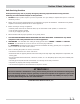
Section 1 Basic Information Safe Servicing Practices Avoid personal injury and/or property damage by observing important Safe Servicing Practices. Following are some limited examples of safe practices: 1. DO NOT attempt a product repair if you have any doubts as to your ability to complete the repair in a safe and satisfactory manner. 2. Always Use The Correct Replacement Parts as indicated in the parts documentation. Substitutions may defeat compliance with Safety Standards Set For Home Appliances. 3.
Section 1 Basic Information Table of Contents Section 1 Basic Information Safe Servicing Practices ........................................... Table of Contents.................................................... Warnings and Cautions ............................................ Safety Instructions .................................................. Protect Children ...................................................... Prevent Fire ............................................................
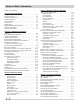
Section 1 Basic Information Section 4 Component Teardown Light Assembly (All Models) ..................................... Door Switch (All Models) ......................................... Front Panel (All Models) .......................................... Front Air Duct (All Models)....................................... Outlet (Exhaust) Thermistor (All Models) .................. Rear Panel (All Models) ........................................... Moisture Sensing Bar (All Models) .........................
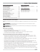
Section 1 Basic Information WARNING To prevent personal injury or damage to the dryer, the electrical power cord of a gas dryer must be plugged into a properly grounded and polarized 3-prong outlet. The third grounding prong must never be removed. Never ground the dryer to a gas pipe. Do not use an extension cord or an adapter plug. ALWAYS disconnect the dryer from the electrical supply before attempting any service or cleaning. Failure to do so can result in electrical shock or injury.
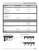
Section 1 Basic Information Electric Models Gas Models 120/208 or 120/240 30 160-350 Watts 3200/4500 ------- 120 15 160-350 Watts ---20,000 Yes Drive Motor (120Volt, 60Hz, 1/4hp 1725RPM) Motor Start Winding Motor Run Winding 4.5 Ohms 3.8 Ohms 4.5 Ohms 3.8 Ohms Heating Element 12.8 Ohms ---- 50,000 Ohms ± 5% @ 77°F 50,000 Ohms ± 5% @ 77°F ---------- 50-400 Ohms 1200 Ohms 1320 Ohms Maximum Medium Low 120° - 160° 110° - 140° 95° - 130° 120° - 180° 105° - 145° 95° - 130° Drum Size 5.8 Cu. Ft.
Section 1 Basic Information Affinity Series Dryer Model Features Gallery Series Dryer Model Features 5.8 Cu. Ft.
Section 1 Basic Information How The Dryer Works Airflow problems: Clothes dryers remove moisture from clothes by pulling air, either warmed or room temperature, through the clothes while they are being tumbled by a turning drum. The moisture from the clothes is exhausted through the dryer vent system to the outside of the house.
Section 1 Basic Information Major Appliance Warranty Information Your appliance is covered by a one year limited warranty. For one year from your original date of purchase, Electrolux will pay all costs for repairing or replacing any parts of this appliance that prove to be defective in materials or workmanship when such appliance is installed, used and maintained in accordance with the provided instructions. Exclusions This warranty does not cover the following: 1.
Section 2 Installation Information WARNING To reduce the risk of fire, electrical shock, or injury when using a Frigidaire Dryer, follow basic safety precautions including the following: - Read all instructions before operating the dryer. - Before performing any type of service or installation, make sure that electric power to the dryer is disconnected.
Section 2 Installation Information Pre-Installation Requirements Tools and materials needed for installation: • Adjustable pliers • Phillips, straight, & square bit screwdrivers • Adjustable wrench • Pipe wrench for gas supply (gas dryer) • LP-resistant thread tape (for natural gas or LP supply, gas dryer) • Carpenter’s level • External vent hood • 4-inch (10.2 cm), rigid metal or semi-rigid metal exhaust duct work • 3-wire or 4-wire 240 volt cord kit (electric dryer) • 4 in. (10.
Section 2 Installation Information Affinity Series 50.8” (129cm)* to clear open door 27.0” (68.5cm) 29.75” (75.5cm)* to front of closed door 36.0” (91.5cm) electrical supply on rear of unit 51.25” (130cm) centerline height for rear vent gas supply pipe on rear of gas unit freestand dryer on floor 3.7” (9.5cm) floor line 1.6” (4cm) dryer mounted on optional pedestal 19.0” (48cm) 16.9” (43cm) floor line * To obtain these minimal depth dimensions, dryer must be vented straight back.
Section 2 Installation Information Gallery Series Dryer Installation Dimensions Free-Standing & Under Counter Electrical supply on rear of unit 360.” 48.5” To clear open door (123.19cm) Gas supply pipe on rear of unit 5.0” (12.7cm) Center line height for rear, right, left vent 36" (91.44cm) (5.72cm) 2.25” 2.375” (6.03cm) 4.375” To side exhausts (11.12cm) (72.39cm) 28.5” 5.875” To base exhaust (14.93cm) 13.5” To rear & base exhausts (34.29cm) 27.0” 27.25 to front of cabinet (69.22cm) 27.
Section 2 Installation Information Exhaust System Requirements Use only 4 inch (10.2 cm) diameter (minimum) rigid or flexible metal duct and approved vent hood which has a swing-out damper(s) that open when the dryer is in operation. When the dryer stops, the dampers automatically close to prevent drafts and the entrance of insects and rodents. To avoid restricting the outlet, maintain a minimum of 12 inches (30.5 cm) clearance between the vent hood and the ground or any other obstruction.
Section 2 Installation Information Install Male Fittings in Correct Direction: Exhaust Direction In installations where the exhaust system is not described in the charts, the following method must be used to determine if the exhaust system is acceptable: (See Figure 2-4) Directional exhausting can be accomplished by installing a quick-turn 90° dryer vent elbow directly to exhaust outlet of dryer. Dryer vent elbows are available through your local parts distributor or hardware store.
Section 2 Installation Information Clearance Requirements Installation in a Recess or Closet 1. A dryer installed in a bedroom, bathroom, recess or closet, MUST be exhausted out doors. 2. No other fuel burning appliance shall be installed in the same closet as the gas dryer. 3. The dryer needs the space around it for proper ventilation. DO NOT install dryer in a closet with a solid door. 4. Closet door ventilation required: A minimum of 120 square inches (774.
Section 2 Installation Information NOTE Because of potentially inconsistent voltage capabilities, the use of this dryer with power created by gas powered generators, solar powered generators, wind powered generators or any other generator other than the local utility company is not recommended. GFI (Ground Fault Interrupter) receptacle is not required. Electrical System Requirements Circuit - Individual 30 amp. branch circuit fused with 30 amp. time delay fuses or circuit breakers.
Section 2 Installation Information WARNING Do not use an extension cord with this dryer. Some extension cords are not designed to withstand the amounts of electrical current this dryer utilizes and can melt, creating electrical shock and/or fire hazard. Locate the dryer within reach of the receptacle for the length power cord to be purchased, allowing some slack in the cord. A U.L.-approved strain relief must be installed onto power cord.
Section 2 Installation Information Electrical Connection (non-Canada) 3 Wire Cord WARNING 30 Amp NEMA 10-30 Neutral (Center Wire) ELECTRICAL SHOCK HAZARD Failure to disconnect power source before servicing could result in personal injury or even death. 1. Turn off power supply to outlet. 2. Remove the screw securing the terminal block access cover in the lower corner on the back of the dryer. 3.
Section 2 Installation Information Electrical Connection (non-Canada) 4 Wire Cord WARNING Ground Green wire 30 Amp NEMA 14-30 ELECTRICAL SHOCK HAZARD Failure to disconnect power source before servicing could result in personal injury or even death. 1. Turn off power supply to outlet. 2. Remove the screw securing the terminal block access cover in the lower corner on the back of the dryer. 3.
Section 2 Installation Information Gas Supply Requirements WARNING EXPLOSION HAZARD Uncoated copper tubing will corrode when subjected to natural gas, causing gas leaks. Use ONLY black iron, stainless steel, or plastic coated brass piping for gas supply. 1. Installation MUST conform with local codes, or in the absence of local codes, with the National Fuel Gas Code, ANSI Z223.1 (latest edition). 2. The gas supply line should be 1/2 inch (1.27cm) pipe. 3.
Section 2 Installation Information General Installation 1. Connect the exhaust duct to the outside exhaust system. Use of a 4” (10.2 cm) clamp is recommended to connect the dryer to the exhaust vent system. Use metal foil tape to seal all other joints. (See Figure 2-15) 2. Carefully slide the dryer to its final position. Adjust one or more of the legs until the dryer is resting solidly on all four legs. Place a level on top of the dryer. The dryer MUST be level and resting solidly on all four legs.
Section 2 Installation Information Reversing the Door Removing the door 1. Protect flat work surface, such as top of dryer or floor near dryer, with a soft cloth or towel. 2. Open dryer door and remove the two hinge screws. Remove lower screw first, then upper screw. (See Figure 2-17) 3. Supporting door with both hands, squarely lift door and hinge upward approximately 3/8” (10 mm) so “T” post on back of hinge can slide out through “T” slot on front panel. (See Figure 2-18) 4.
Section 2 Installation Information Reversing the Hinge 1. Carefully pull out the 2 small round hole plugs from the front panel and save. Remove and save the square “T” slot cover by sliding it up and pulling it out. Move all 3 plugs to the opposite side of the front panel and insert. (See Figure 2-20) 4. From the back side of the inner door, pinch the retaining tabs of the plastic square plug to release it. Save square plug for reinstallation.
Section 2 Installation Information Reassembling the Door 1. Locate and remove the hinge cutout gate from the outer door assembly. Rotate and move it to the opposite hole in the outer door. (See Figure 2-26) 3. Replace indented head screws (no. 1-5) removed earlier. Take care not to strip out the plastic holes. (See Figure 2-28) 4. Replace pan head screws (no. 6-7) removed earlier. Take care not to strip out the plastic holes. (See Figure 2-28) no. 1-5 no. 6-7 Figure 2-26. 2.
Section 2 Installation Information Reattaching the Door 1. Holding the door in both hands, squarely insert the “T” post on the back of the hinge into the “T” slot on the front panel and lower it to align the mounting holes. (See Figure 2-30) 3. Close the door and test operation of hinge, strike and latch. (See Figure 2-32) “T” Slot In Front Panel “T” Post On Door Hinge Figure 2-32. Figure 2-30. 2. Rest the opening of the inner door at a 90 degree angle on the “shoulders” of the hinge cutout gate.
Section 2 Installation Information Accessories 27.0 (68.5 0” 8cm ) Matching Storage Pedestal Arctic White Pedestal - P/N APWD15W Black Diamond Pedestal - P/N APWD15E A storage pedestal accessory, specifically designed for this dryer may be used to elevate the dryer for ease of use. This pedestal will add about 15” (38 cm) to the height of your unit for a total height of 51.25” (130 cm). 15.0 (38.
Section 2 Installation Information Washer and Dryer 15” Drawer Pedestal Installation The Affinity Series washers and dryers use the same pedestal. Tools needed: Level 9/16” open end wrench #2 Phillips screwdriver Washer/Dryer Installation Kit Screws Screws Rear Bracket Rear Bracket Foam Pedestal Top NOTE This kit is intended to be installed by persons having electrical and mechanical training and a level of knowledge considered acceptable in the appliance repair trade.
Section 2 Installation Information Pedestal Installation 5. Set the dryer down onto the pedestal making sure the dryer base is behind the front brackets of the pedestal. 6. Align the sides of the dryer with the sides of the pedestal and attach the dryer to the rear brackets using four #10 screws (2 per bracket) as shown in Figure 2-36. 7. With pedestal drawer open for better access, install the two #10 screws through the front brackets in the pedestal into the dryer base as shown in Figure 2-37. 8.
Section 2 Installation Information The Gallery Series dryers are designed so the door swing may be reversed at any time without additional parts. Conversion is accomplished by transferring hinges to the opposite side of the cabinet. “Solid Door” Reversal Instructions: 1. Screws Open the dryer door. Remove the four hinge hole plugs from the left side of the door opening. Retain the plugs for use later. NOTE A plastic knife may be needed to help pull out the plugs. Use caution not to scratch the paint. 2.
Section 2 Installation Information 7. 8. Install the handle and screws removed in Step 4. Remove the two hinges and reinstall the four screws. Note the installation orientation of the hinges. (See Figure 2-41) 9. Remove the screws from the opposite side of the door and use them to reinstall the hinges. 10. Install the door assembly on the left side of the door opening using the four screws removed in Step 1. Hinges Figure 2-41.
Affinity Series Section 3 Electronic Control Affinity Control Panel Layout Cycles with Light Indicators Temperatures with Light Indicators Dryness Level with Light Indicators Dryer Features with Light Indicators LED Timer Status Lights Cycle Selection Knob Operating Steps User Interface Buttons Figure 3-1. Affinity Control Panel 1. 2. 3. 4. Prepare items for drying. Check that lint filter is clean and in place. Load the dryer. If desired, add a dryer fabric softener sheet. Close the door.
Section 3 Electronic Control Cycle Description Affinity Series Towel Cycle Selected Auto Dry Loads dried using the Towels, Heavy Duty, Normal, Perm Press, and Delicates cycles will dry automatically at the selected temperature to the desired dryness level. The dryer uses sensing bars to sense the moisture level of the load as it tumbles through heated air. Auto Dry cycles save time and energy and protect fabrics.
Affinity Series Section 3 Electronic Control Drying Temperature Maximum Temperature Selected For best results, follow fabric care label instructions on items to be dried. To change the drying temperature, press the TEMPERATURE button to scroll to the desired heat. To protect your wardrobe, not all temperatures are available with every cycle. (See Figure 3-3) Maximum heat is recommended for sturdy fabrics. High heat is recommended for most cotton fabrics.
Section 3 Electronic Control Options Affinity Series Shrink Guard Selected To select an option, press OPTIONS until the indicator for the desired option flashes, then press SELECT. If an option is not available for a cycle, the indicator will not light. Follow the same steps to delete an option. (See Figure 3-5) Select Shrink Guard to lower the initial drying temperature to protect fabrics from over dying. Select Extended Tumble if the dried load might not be removed promptly at the end of the cycle.
Affinity Series Section 3 Electronic Control Cycle Options Appropriate drying Temperature, Dryness Level and Options will automatically be displayed for each cycle. The settings can be changed before the cycle is started. Those adjustments will automatically be remembered each time that cycle is selected. If a temperature, dryness level or option is not recommended for a cycle, the indicator will not light.
Section 3 Electronic Control Testing Affinity Series Reading Error Codes - Affinity Models 1. 2. 3. Press and hold the SELECT and CANCEL buttons simultaneously for 6 seconds to reset control. The buzzer will sound 1 time and “rES” will be shown briefly in the display. Immediately after, rotate cycle selector knob 2 turns counter-clockwise to the third position from the top, and then press and hold the SELECT and CANCEL buttons simultaneously for 6 seconds.
Affinity Series Error Code Label Section Section 3 Electronic 3 Electronic Control Testing Control Description Solution E10 General Problem with communication Clear code, exit mode and start dryer. If problem persists, replace electronic between EEPROM and the control. microprocessor. E11 Checksum Problem with communications Clear code, exit mode and start dryer. If problem persists, replace electronic or memory did not check, control. one has become corrupted.
Section 3 Electronic Control Gallery Series Gallery Series Control Panel Layout Temperatures with Light Indicators Dryness Level with Light Indicators Dryer Features with Light Indicators LED Timer Status Indicators Cycle Selection Knob Operating Steps 1. 2. 3. 4. 5. 6. 7. 8. 9. User Interface Buttons Figure 3-7. Gallery Control Panel Prepare items for drying. Check that lint filter is clean and in place. Load the dryer. If desired, add a dryer fabric softener sheet. Close the door.
Gallery Series Section 3 Electronic Control Cycle Descriptions Normal Cycle Selected Auto Dry Applies to Towels, Bulky, Normal, Perm Press, Sport and Delicate cycles. Auto Dry cycles take the guesswork out of drying time. The load will automatically be dried at the selected temperature to the desired dryness level. The dryer senses the moisture level of the load as it tumbles through heated air. Auto Dry cycles save time and energy and protect fabrics.
Section 3 Electronic Control Gallery Series Drying Temperature High Temperature Selected For best results, follow fabric care label instructions on items to be dried. To change the drying temperature, press the TEMP button to scroll to the desired heat. To protect your wardrobe, not all temperatures are available with every cycle. (See Figure 3-3) High heat is recommended for sturdy fabrics. Medium High heat is recommended for most cotton fabrics.
Gallery Series Options Section 3 Electronic Control Shrink Guard Selected To select an option, press OPTIONS until the indicator for the desired option flashes, then press SELECT. If an option is not available for a cycle, the indicator will not light. Follow the same steps to delete an option. (See Figure 3-5) The Cycle Signal will sound at the end of the cycle and periodically during Press Saver. Select SHRINK GUARD to lower initial drying temperature to protect fabrics from over-drying.
Section 3 Electronic Control Gallery Series Dryer Settings Chart Available Cycle Settings - These temperatures, dryness levels and options areavailable with the following cycles: E s ti m a te d d r y i n g ti m e *** To w els N o rm a l P e rm P re s s D e l i c a te Q uic k B ulky Tim e d D ry 60 minute s 50 minute s 4 0 minute s 2 0 minute s 3 0 minute s 45 minute s 1 5 to 9 0 minute s T e m p e r a tu r e s H ig h * * M e dium-H igh * * M e d iu m * * * L ow ** ** N o H eat D
Error Codes - Gallery Series Section 3 Electronic Control Reading Error Codes - Gallery Series 1. Non-Digital Readout Display Models: Rotate cycle selector knob to the 3 O’clock position. Digital Readout Display Models: Rotate cycle selector knob clockwise (3) settings from the Normal cycle option. 2. Press and hold the Select and Pause Cancel buttons simultaneously for six seconds. 3. Immediately after, press and hold the START and Pause Cancel buttons simultaneously for 4 seconds. 4.
Section 3 Electronic Control Error Codes - Gallery Series Function Test Sequence 1. Non-Digital Readout Display Models: Position the cycle selector knob to the 12 O’clock position. Digital Readout Display Models: Position the cycle selector knob to the Normal cycle option. 2. Press and hold the SELECT and PAUSE CANCEL buttons simultaneously for six seconds. 3. Immediately after, press and hold the START and PAUSE CANCEL buttons simultaneously for 4 seconds.
Error Codes - Gallery Series Error Code Label Description Section 3 Electronic Control Solution E10 General Problem with communication Clear code, exit mode and start dryer. If problem persists, replace electronic between EEPROM and the control. microprocessor. E11 Checksum Problem with communications Clear code, exit mode and start dryer. If problem persists, replace electronic or memory did not check, control. one has become corrupted.
Section 3 Electronic Control Testing Electrical Operation (Electric Dryers Models) When the dryer is connected to electrical power, line 1 is connected to one side of the thermal limiter and the COM terminal of the heater relay RL2 that is mounted on the electronic control board. (See Section 6 Wiring Diagrams or Wiring Schematic provided with the unit) Power is applied to the control board through thermal limiter to pin 1 of the eight pin plug.
Section 3 Electronic Control Testing Drying Time: Drive Motor Circuit: The amount of drying time is determined in one of two ways: When power is connected to the dryer, line 1 is applied to the COM terminal of the door switch. When the door is closed, the COM terminal is connected to terminal NO of the door switch. From terminal NO, power is applied to terminal J4-2 of the control board to the motor relay RL1 on the control board.
Section 3 Electronic Control Testing The Heating Circuit: The electronic control board applies power to the heating circuit through the contacts of relay RL 2. When the electronic control senses that the temperature in the drum is below the programmed temperature, it closes the contact of heater relay RL2 applying line 1 to the high limit thermostat. The high limit thermostat is a safety device that prevents the dryer from overheating if the contacts of the relay RL2 fail closed.
Section 3 Electronic Control Testing Electrical Tests For Electric Dryers Only High Limit Thermostat Cycle Time Trip: Run the following test at room temperature. Set the Time Dry cycle for 30 minutes and the heat selection at maximum setting. Place a 100% exhaust block on the exhaust pipe. The dryer door should be open for this test and the door switch held closed by tape or similar means. The thermostat must open (heater off) between 35 to 120 seconds.
Section 3 Electronic Control Testing Motor Protector Trip Time When the motor is locked, the thermal protector must open to shut off motor within 3 to 10 seconds. This test also applies to the 50/60 Hz Motor when test is conducted at 230VAC 60 Hz. Tests must be run at 120VAC (line voltage not to sag below this value when the rotor is locked), unless specified otherwise. NOTE Tests must be run with a cold (ambient) motor.
Section 3 Electronic Control Testing Drum Temperatures The following tests should be run with an unrestricted exhaust. The location of the thermal couple is to be the square in the lint grill which is 12 squares left from the right edge of the lint blade and (2) squares forward. The tip should extend 1.25” into the air grill. Set the dryer timer as needed for each test. The recordable temperature is to be the maximum temperature following the heater off of the 3rd cycle.
Section 3 Electronic Control Testing Electric dryer completely inoperative. Note: Always check wiring to the components. Note: If a fault code is displayed, the dryer will not operate. Dryer completely inoperative. Does the control beep or the LED flash when the start button is pushed.? No. 0. Yes. Measure the voltage drop between the red wire on the thermal limiter and neutral. Is an error code displayed? Yes. 120VAC.
Section 3 Electronic Control Testing Gas dryer completely inoperative. Note: Always check wiring to the components. Note: If a fault code is displayed, the dryer will not operate. Dryer completely inoperative. Does the control beep or the LED flash when the start button is pushed.? No. Yes. Is an error code display. Measure the voltage drop between pins 1 & 2 of the eight pin plug of the wire harness to the control board. Yes. No. 0.
Section 3 Electronic Control Testing Electric and Gas dryers; blower motor runs but drum does not turn. Note: Always check wiring to the components. Drive motor runs but drum does not turn. Belt broken or off pulley. Electric and Gas dryers; longer than normal drying times. (Possible E 4A) Note: Always check wiring to the components. Longer than normal drying times. Yes. Are the clothes wetter than normal when removed from the washer? Check washer spin cycle. No. Is the vent restricted? Yes.
Section 3 Electronic Control Testing Electric dryers not heating properly (Possible E 5b) Note: Always check wiring to the components. Electric dryer not heating properly. Program the dryer for a Normal Cycle with High Temp and touch Start . Measure the voltage drop between L1 and L2 at the terminal block. Below 215 VAC. Have customer check house wiring. Above 215 VAC. Measure the voltage drop between two terminals of the heating element. Not the same as between L1 & L2.
Section 3 Electronic Control Testing Gas dryers not heating properly. (Possible E 5b) Note: Always check wiring to the components. Gas dryer not heating properly. Program the dryer for a Normal Cycle with Low Temp and touch Start . Listen to hear if the burner cycle. Burner does not cycle. Burner cycle. Check the burner area for soot. Is the burner burning clean? Yes. Check the resistance of the control thermistor at room temperature. No. 53000 Ohms +/- 10%. Clean the orifice and check the valve.
Section 3 Electronic Control Testing Electric dryers; drive motor runs but dryer does not heat. Note: Always check wiring to the components. Drive motor runs but dryer does not heat. Program the dryer for a Normal Cycle with High Temp and touch Start . Measure the voltage drop between the two terminals of RL 2. 240 VAC. Defective electronic control board. 0. Measure the voltage drop between the two terminals of the high limit thermostat. 240 VAC. Defective high limit thermostat. 0.
Section 3 Electronic Control Testing Gas dryers; drive motor runs but dryer does not heat. Note: Always check wiring to the components. Drive motor runs but dryer does not heat. Program the dryer for a Normal Cycle with High Temp and touch Start . Measure the voltage drop between the two terminals of RL 2. 120 VAC. Defective electronic control board. Igniter glows full brilliance or glows dim the full minute.
Section 3 Electronic Control Testing Electric and Gas dryers; clothes not dry in auto cycle. Note: Always check wiring to the components. Clothes not dry in the auto cycle. Tested good. Using the on function test do the 3 O’clock test. (Refer to pages 8) Check that the dryer is level or slightly tip forward. Failed test. Are the sensor bars clean? No. Clean bars. Yes. Check the connections at the bars and the wiring between the control and the bars. Checks good. Replace the electronic control.
Section 3 Electronic Control Testing Electric and Gas dryers; selector LEDs do not light. Note: Always check wiring to the components. Selector LEDs do not light. Yes. Defective interface board. Defective harness. Repair or replace harness. Do any of the LEDs light No. Check the wiring harness between the control board and the interface board. Good harness. Replace the interface board. If this does not correct the problem, replace the control board.
Section 4 Component Teardown Component Teardown This section explains how to access and remove components from a Frigidaire Affinity or Gallery Series Dryer, and has been arranged in such a way as to simulate which components would need to be removed first in order to gain access to other components. When following a component removal procedure, it may be necessary to reference another component removal procedure listed earlier in this section.
Section 4 Component Teardown This section will describe how to access and remove serviceable components from the dryer. Unless stated, the procedure will be the same on all models. Unless stated, reverse the procedure to reinstall the component. Removing the Door (Affinity Models) 1. Protect a flat work surface, such as top of dryer or floor near dryer, with a soft cloth or towel. 2. Open dryer door and remove the two hinge screws with a Phillips screwdriver. Remove lower screw first, then upper screw.
Section 4 Component Teardown Removing the Door Strike and Hinge Assembly (Affinity Models) To access the door strike and hinge assembly, the door must be removed from the unit and the inner and outer panels separated. 1. Turn inner door assembly over to expose retaining tabs of metal door strike. Grip tabs with pliers, compress and push through door panel. (See Figure 4-4) 2. Turn the inner door assembly back over and locate the 2 pan head hinge screws.
Section 4 Component Teardown Hinge Removal (Gallery Models) The hinges are removed by extracting the two screws using a Phillips head screwdriver that secure each hinge to the door assembly. (See Figure 4-8) Door Assembly Breakdown (Gallery Models) The door assembly consists of two panels, the outer lens, the inner glass with adapting mounting bracket and the door strike. The door assembly must be removed to access the door assembly components.
Section 4 Component Teardown Top Panel Removal (All Models) Screws The top panel is removed by extracting the two #2 square bit screws located along the rear edge of the top panel. (See Figure 4-11) With the screws removed, slide the top panel towards the rear until free of the retaining clips located at the front of the side panels. Figure 4-11.
Section 4 Component Teardown Control Board Housing Removal (Gallery Models) Electrical Connections Affinity Models Only The control board housing is secured to the console panel with five screws and five retaining tabs. To remove the control board housing: 1. Disconnect the dryer from electrical supply and remove the top panel and console panel. 2. Disconnect all wire leads from console panel. (See Figure 4-14) 3.
Section 4 Component Teardown Light Assembly Removal (All Models) Tab The light assembly is secured with a retaining tab to the inner front panel. A plastic lens is secured to the light assembly with three retaining clips which provides light to the drum. The light assembly is only accessible by removing the console panel. To remove the light assembly: 1. Disconnect the dryer from electrical supply and remove the top panel and console panel. 2.
Section 4 Component Teardown Front Panel Removal (All Models) The front panel is secured with four screws, two screws at each top corner and two along the bottom flange. Two guide clips mounted to the inner edge of the front panel slide into slots cut in the cabinet frame. To remove the front panel: 1. Remove the door assembly and air duct cover. 2. Remove top panel and console, then disconnect door switch wire leads from drum light and wire harness. 3.
Section 4 Component Teardown Rear Panel Removal (All Models) The rear panel is secured with 17 screws to the unit frame. The exhaust duct will need to be removed prior to removing the rear panel. The electrical connections must be disconnected from the unit behind the access cover located on the rear panel. Electric heater models require that the power cord is disconnected from the terminals as shown in Figure 4-24.
Section 4 Component Teardown Belt Removal (All Models) Belt The belt circles the drum and has tension applied to it by a spring mounted between the idler arm assembly and the motor mount. To remove the belt: 1. Disconnect the dryer from electrical supply, then remove the top panel, rear panel, console and front panel. 2. From the rear of the unit, reach under the drum and pull the idler arm assembly to the right and release the belt from the roller guides and motor pulley.
Section 4 Component Teardown Roller Assembly Removal (All Models) There are five roller assemblies that the dryer drum rides upon. The roller shafts are secured to the outside of the inner panels by a 9/16” nut. The rollers slide onto roller shafts and are secured with triangular retainers. To remove the roller assemblies: 1. Disconnect the dryer from electrical supply, then remove the top panel, rear panel, console, front panel, front inner panel and drum. 2.
Section 4 Component Teardown Exhaust Tube Removal (All Models) The exhaust tube is secured at the rear of the unit with a screw to the unit base. A rubber seal slides over the connection between the exhaust tube and the blower assembly. To remove the exhaust tube: 1. Disconnect the dryer from electrical supply, then remove the top panel, rear panel, console, front panel, front inner panel and drum. 2. Disconnect the wire leads from the exhaust thermal limiter terminals.
Section 4 Component Teardown Motor and Blower Assembly Removal and Separation (All Models) To remove the motor and blower assemblies: 1. Disconnect the dryer from electrical supply, then remove the top panel, rear panel, console, front panel, front inner panel and drum. 2. Disconnect wire harness connection from the motor. (See Figure 4-33) 3. Using a 7/8” extended socket and while holding the motor shaft from turning, loosen the blower wheel from the shaft by turning clockwise.
Section 4 Component Teardown Heat Shield Removal (All Electric Models) NOTE Screw If unit was used prior to service, the heater assembly may be hot. Refer to Warnings and Cautions at the beginning of this section. The heat shield is secured with a screw to the mounting bracket for the heater assembly. To remove the heat shield: 1. Disconnect the dryer from electrical supply, then remove the top panel, rear panel, console, front panel, front inner panel and drum. 2.
Section 4 Component Teardown Thermal Limiter and Safety Thermostat Removal (All Electric Models) The thermal limiter and safety thermostat are mounted to the left side of the heater assembly and secured in position with screws. Safety Thermostat To remove the thermal limiter and safety thermostat: 1. Disconnect the dryer from electrical supply, then remove the top panel, rear panel, console, front panel, front inner panel and drum. 2.
Section 4 Component Teardown Gas Valve Wire Harness Connections (All Gas Models) To remove the wire harness connections: 1. Disconnect the dryer from electrical supply, then remove the top panel, rear panel, console, front panel, front inner panel and drum. 2. Label the connections as needed prior to disconnecting. 3. Disconnect at the Molex connectors for the ignitor, sensor and main wire harness. (See Figure 4-41) 4. Disconnect wire leads from gas valve coil terminals.
Section 4 Component Teardown Manifold and Burner Assembly Breakdown (All Gas Models) Valve Mounting Bracket Screws In order to separate the manifold from valve body, the burner assembly must be removed from the valve body. A screw at the rear of the unit secures the manifold to rear frame as well as two screws securing the manifold to unit base. All electrical connections must be disconnected prior to removing the manifold. To remove the manifold and burner assembly: 1. Shut off gas supply to dryer. 2.
Section 4 Component Teardown Combustion Tube Removal ( All Gas Models) The combustion tube is secured to a mounting bracket in the front and secured with two screws. The rear of the combustion tube slides into the heat duct and is secured with a screw to the right rear of the combustion tube. To remove the combustion tube: 1. Remove the top panel, rear panel, console, front panel, front inner panel and drum. 2. Remove burner and gas valve assembly. 3.
Section 5 Troubleshooting The following troubleshooting chart involves problems arising from improper drying techniques and are not valid service issues. Many drying problems involve poor cleaning results, poor soil and stain removal, residues of lint and scum, and fabric damage. For satisfactory drying results, follow these suggestions provided by The Soap and Detergent Association. For Troubleshooting the electronic control and error codes, See Section Three Electronic Control.
Section 5 Troubleshooting The following troubleshooting chart involves common concerns that are not the result of defective workmanship or materials in this dryer. Some problems below involve improper installation and issues arising from the users household water supply. See the Use and Care guide for the unit in question and the Installation Section in this manual. Problem Dryer does not start. Cause Correction 1. Electrical power cord is not securely plugged in or plug may be loose. 2.
Section 5 Troubleshooting Problem Cause Scratching or 1. Foreign objects such as coins, chipping of the drum pins, clips or buttons are inside finish. the dryer.* 2. Permanently attached items such as belt buckles, zippers and fasteners may be hitting the inside of the drum.* Correction 1. Always remove foreign objects from pockets before laundering. Remove objects from drum and restart dryer. 2.
Section 5 Troubleshooting Electrical Tests For Electric Dryers Only High Limit Thermostat Cycle Time Trip: Run the following test at room temperature. Set the Time Dry cycle for 30 minutes and the heat selection at maximum setting. Place a 100% exhaust block on the exhaust pipe. The dryer door should be open for this test and the door switch held closed by tape or similar means. The thermostat must open (heater off) between 35 to 120 seconds.
Section 5 Troubleshooting Electrical Tests For Gas Dryers Manifold Pressure Connect manometer to pressure tap on gas valve. During burner operation, manometer reading should be between 2.9 and 4.0 inches of gage oil. Flames Entering Drying Chamber Block exhaust and inspect flame length. The flames should not be entering the drying chamber. Flash Back Into Burner With exhaust blocked, inspect for flash back into burner during ignition. Flame Failure Shut off manual gas valve to extinguish flame.
Section 5 Troubleshooting Electrical Tests For Gas Dryers Thermal Limiter Trip Time Run the following test at room temperature. Set the Time Dry cycle for 30 minutes and the heat selection at maximum setting. Place a 100% exhaust block on the exhaust pipe. The dryer door should be open for this test and the door switch held closed. The thermal limiter should trip and shut the dryer off after 1 to 5 minutes of operation.
Section 6 Wiring Diagrams Affinity Series With Electric Heater 6-1
Section 6 Wiring Diagrams Affinity Series With Gas Heater 6-2
Section 6 Wiring Diagrams Gallery Series With Electric Heater 6-3
Section 6 Wiring Diagrams Gallery Series With Gas Heater 6-4