2020 D Cooker Hood Operating and Installation Instructions
For the User For the Installer Important Safety Information Installation Instructions Technical Information Your Appliance Electrical Connections Electrical Requirements Electrical Connection Operating Instructions Cooker Hood Controls To Operate Recirculation Extraction Installing the Cooker Hood Service and Spare Parts Installation Requirements Unpacking Clearance Height Selecting the Type of Installation Fixing the Chimney to the Canopy Fitting the Hood to the Wall Drilling the Shelves Bottom She
IMPORTANT SAFETY INFORMATION These warnings are provided in the interests of your safety. Ensure that you understand them all before installing or using this appliance. Your safety is of paramount importance. If you are unsure about any of the meanings of these warnings contact the Customer Care Department. Installation • • • • • • • • • • • Child Safety Any installation work must be undertaken by a qualified electrician or competent person.
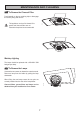
YOUR APPLIANCE OPERATING INSTRUCTIONS This cooker hood is designed to extract unpleasant odours from the kitchen, it will not extract steam. To obtain the best performance it is advisable to switch on the hood a few minutes before you start cooking and leave it running for approximately 15 minutes after finishing. Cooker Hood Controls V1. V2. V3. L. Push to engage the low speed, for use with one burner or simmering. Push to engage the medium speed, for normal cooking up to four pans.
OPERATING INSTRUCTIONS This cooker hood can be used to recirculate or extract contaminated air. Recirculation The cooker hood is supplied specified for use in the recirculation mode with the charcoal filter fitted. The contaminated air is cleaned by passing through the filters and than back into the kitchen. S07_29 The activated charcoal filter absorbs odours arising from cooking. In use it will slowly become saturated in grease and less effective.
MAINTENANCE AND CLEANING Before carrying out any maintenance or cleaning isolate the cooker hood from the mains supply. The cooker hood must be kept clean, a build up of grease or fat can be a fire hazard. External Cleaning S07_06 The metal casing, grille and chimney should be cleaned at least once a month to keep it looking like new. Wipe over the hood with a soft cloth wrung out in mild soapy water and then dry thoroughly.
MAINTENANCE AND CLEANING To Remove the Charcoal Filter Push inwardly on the two retaining clips to disengage the security fixing and remove. S07_27 This appliance can be a fire hazard if the grease and charcoal filters are not cleaned and replaced as recommended. S07_31 Worktop Lighting The lamps should be replaced with a 220-240V 20W halogen spot lamp. To Remove the Lamps Unscrew the two screws to release the metal surround. Remove a lamp from the holder by pulling the lamp downwards.
SOMETHING NOT WORKING If, having followed these instructions carefully, your cooker hood fails to work properly please carry out the following checks. Solution Symptom The cooker hood will not start • Check the hood is connected to the electricity supply. • Check that the fan speed control is set to 1, 2 or 3. The cooker hood is not working effectively • The fan speed is set high enough for the task. • The grease filter is clean. • The kitchen is adequately vented to allow the entry of fresh air.
GUARANTEE CONDITIONS Standard Guarantee Conditions We, AEG, undertake that if within 12 months of the date of the purchase this AEG built-in appliance or any part thereof is proved to be defective by reason only of faulty workmanship or materials, the company will, at our option, repair or replace the same FREE OF ANY CHARGE for labour, materials and carriage on condition that: • The appliance has been correctly installed and used only on the electrical supply stated on the rating plate.
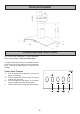
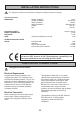
INSTALLATION INSTRUCTIONS It is dangerous to alter the specifications or attempt to modify this product in any way. Technical Information DIMENSIONS HEIGHT (CANOPY): HEIGHT (CHIMNEY): WIDTH (CANOPY): WIDTH (CHIMNEY): GROSS: NET: ELECTRICAL SUPPLY: POWER CONSUMPTION: FAN MOTOR: LAMP: (2x20W) HALOGEN Ø 35 mm GUA SUITABLE FOR INSTALLATION ABOVE: 73 mm 450-850 mm 898 mm Ø200-Ø270 mm 24.
INSTALLING THE COOKER HOOD Please ensure that when the appliance is installed it is easily accessible to an engineer in the event of a breakdown. All installations must comply with the local authorities requirements for the discharge of exhaust air. Incorrect installation may affect the safety of this cooker hood. Installation Requirements Before installation check the wall to which the cooker hood is to be fitted for electric cables, water pipes or gas.
INSTALLING THE COOKER HOOD Clearance Heights The cooker hood is designed to be fitted over a cooking appliance at the clearance heights stated, provided the maximum output of the appliance beneath does not exceed the maximums quoted in the Technical Specifications. If the output of the appliance below the cooker hood exceeds the maximum outputs quoted, please refer to the cooker manufacturer’s installation instructions.
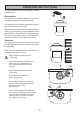
INSTALLING INSTRUCTIONS Fixing the Chimney to the Canopy 1. Remove the metal grease filter cassette by pushing inwardly on the two steel handles. 2. To remove the charcoal filter push inwardly on the two retaining clips to disengage the security fixing and remove. 3. 4. 5. A Align the fixing points on the chimney with the corresponding fixing points on the canopy. Ensure the guide in the two chimney sections is positioned at the back to face the wall.
INSTALLING INSTRUCTIONS 3. Slide the chimney through the hole in the shelf before fixing it to the canopy. Top Shelf The top shelf only requires drilling if the hood is to be installed with the air outlet turned upwards. 1. Use the cardboard template provided to mark the hole position on the shelf. 2. Using the hole ‘B’ as a reference point, drill the shelf along the centre axis for the chimney to pass through.
INSTALLING INSTRUCTIONS Fix the round eyelet screws provided tightly into the holes (1). 6. Fix bracket (S) to the fan assembly. 7. The hood is supplied in the recirculation mode, with the recirculation grille (G) fitted over the outlet in the top of the fan assembly ready for use. 8. Insert the 4.2x44.4mm screws to be used for fixing the fan assembly into the rawl plugs and tighten about two thirds. Lower the fan assembly and chimney onto the fixing bracket (S).
Mark the position on the wall and drill the hole for the ducting. To calculate the centre of the hole on the wall for the ducting, draw a horizontal line (D) through the vertical line 80mm above line (X) The round ducting to be used must be Ø125mm. 6. Fix the round eyelet screws provided tightly into holes (1) and hook on the canopy (C) ensuring the hooks are located into the eyelets before releasing the canopy. 7.
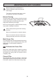
INSTALLING INSTRUCTIONS The hood is supplied with the air outlet facing the rear. To rotate the extractor to face left or right proceed as follows: (A) Loosen the screws (V1), turn the extractor 60° to the left or right as required, then tighten the screws. (B) To fix the bracket (S), select the left or right hand screw holes and using the screw (V2) secure the bracket. 6. Unscrew the four self tapping screws and remove the plastic surround. 7.
INSTALLING INSTRUCTIONS Final fixing and adjustment of the hood: Two adjustable connectors are provided at the rear of the hood. (b) (c) (d) (e) Turn the screws (V1), until the screws (V2) align with the screw holes (F2). Adjust the vertical and horizontal alignment using screws (V2). Turn the screw (V1) to secure the hood to the wall. Insert the plastic grommets provided into the screw holes (F2). Tighten the screws fixing the canopy (C) to the chimney (A).
INSTALLING INSTRUCTIONS Electrical connection and working test: 1. Remove the metal cover by unscrewing the four self tapping screws. 2. Connect the ‘Push-Fit’ connectors coming from the fan assembly to the canopy. 3. Position the terminals as illustrated under the cover and replace the cover with the four self tapping screws. 4. Once the electrical connection has been completed, check that the worktop lighting, fan motor and the speed selection is working properly. 5.
4329477 01 - 001013