
Installation Instructions
1
30" GAS SLIDE-IN RANGE INSTALLATION INSTRUCTIONS
(Models with Sealed Top Burners)
E
E
P/N 318201686 (1302) Rev. D
English – pages 1-12; Español – páginas 13-24;
Français - pages 25-36; Notes - pages 37-38;
Wiring Diagrams - pages 39-40
If the information in this manual is not followed exactly, a fire
or explosion may result causing property damage, personal injury or death.
FOR YOUR SAFETY:
— Do not store or use gasoline or other flammable vapors and liquids in the
vicinity of this or any other appliance.
— WHAT TO DO IF YOU SMELL GAS:
• Donottrytolightanyappliance.
• Donottouchanyelectricalswitch;donotuseanyphoneinyourbuilding.
• Immediatelycallyourgassupplierfromaneighbor'sphone.Followthe
gassupplier'sinstructions.
• Ifyoucannotreachyourgassupplier,calltheredepartment.
— Installation and service must be performed by a qualified installer, service
agency or the gas supplier.
INSTALLATION AND SERVICE MUST BE PERFORMED BY A QUALIFIED INSTALLER.
IMPORTANT:SAVEFORLOCALELECTRICALINSPECTOR'SUSE.
READ AND SAVE THESE INSTRUCTIONS FOR FUTURE REFERENCE.
NOTE: Wiring diagram for these appliances are enclosed in this booklet.
Printed in United States
Appliances Installed in the
state of Massachusetts:
This Appliance can only be installed
in the state of Massachusetts by a
Massachusetts licensed plumber or
gasfitter.
This appliance must be installed
with a three (3) foot / 36 in. long
flexible gas connector.
A"T" handle type manual gas
valve must be installed in the gas
supply line to this appliance.
Refer to your serial plate for
applicable agency certification
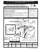
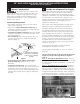
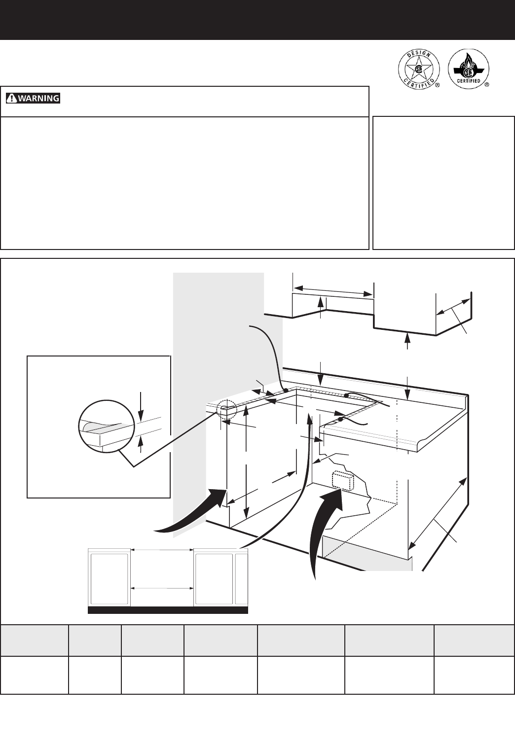
1/2” min.
3/8” min.
1/2” min.
WALL
5" Min.
(12,7 cm Min.)
From Wall Both Sides
30" Min.
(76,2 cm Min.)
18" Min.
(45,7 cm) Min.
Approx. 1 7/8"
(4,8 cm)
Grounded Junction Box or Wall Outlet Should Be
Located 8" to 17" (20,3 cm to 43,2 cm) From Right
Cabinet and 2" to 4" (5,1 cm to 10,2 cm) From Floor.
Locate Cabinet Doors 1" (2,5 cm)
Min. from Cutout Opening.
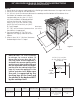
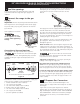
F
G
E
31 1/2"
(81 cm)
Exact
13"
(33 cm)
24" Min.
(61 cm Min.)
Shave
Raised
Edge
to Clear
Space
for a 31½"
(80 cm) Wide
Cooktop.
1 ½" Max.
(3,8 cm Max.)
30" Min.
(76,2 cm) Min.
(see Note 3)
These surfaces should be flat
& leveled (hatched area).
A. HEIGHT B. WIDTH C. COOKTOP
WIDTH
D. DEPTH TO
FRONT OF RANGE
E. CUTOUT WIDTH*
(Countertop and
Cabinet)
F. CUTOUT
DEPTH
G. HEIGHT
OF COUNTERTOP
35 5/8" (90.5 cm)
- 36 5/8" (93 cm)
30" (76,2 cm) 31½" (80 cm) 28 5/16" (71,9 cm) 30±1/16" (76,2±0,15 cm) 21 3/4" (55,2 cm) Min.
22 1/8" (56,2 cm) Max
24" (61 cm) Min. with
backguard
36 5/8" (93 cm) Max.
35 7/8" (91.1 cm)
Min.
IMPORTANT:
Cabinet and
countertop width
should match the
cutout width.