
Installation Instructions
6
30" GAS SLIDE-IN RANGE INSTALLATION INSTRUCTIONS
(Models with Sealed Top Burners)
The supply line must be equipped with an approved
manual shutoff valve. This valve should be located in
the same room as the range and should be in a location
that allows ease of opening and closing. Do not block
access to the shutoff valve. The valve is for turning on or
shutting off gas to the appliance.
Once regulator is in place, open the shutoff valve in the
gas supply line. Wait a few minutes for gas to move
through the gas line.
Check for leaks. After connecting the range to the gas
supply, check the system for leaks with a manometer. If
a manometer is not available, turn on the gas supply and
use a liquid leak detector (or soap and water) at all joints
and connections to check for leaks.
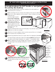
Do not use a flame to check for leaks
from gas connections. Checking for leaks with a flame
may result in a fire or explosion.
Tighten all connections as necessary to prevent gas
leakage in the range or supply line.
Disconnect this range and its individual shutoff
valve from the gas supply piping system during any
pressure testing of the system at test pressures greater
than 1/2 psig (3.5 kPa or 14"(35,56 cm) water column).
Isolate the range from the gas supply piping system
by closing its individual manual shutoff valve during any
pressure testing of the gas supply piping system at test
pressures equal to or less than 1/2 psig (3.5 kPa or 14"
water column).
5
LP/Propane Gas Conversion
This appliance can be used with Natural gas or LP/
Propane gas. It is shipped from the factory for use with
natural gas.
If you wish to convert your range for use with LP/
Propane gas, use the supplied fixed orifices located in a
bag containing the literature marked "FOR LP/PROPANE
GAS CONVERSION." Follow the instructions packaged
with the orifices for surface, oven and broil burners
conversion.
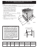
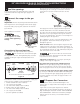
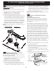
Assemble the flexible connector from the gas supply pipe
to the pressure regulator in the following order:
1. manual shutoff valve (not included)
2. 1/2" nipple (not included)
3. 1/2" flare union adapter (not included)
4. flexible connector (not included)
5. 1/2" flare union adapter (not included)
6. 1/2" nipple (not included)
7. pressure regulator (included)
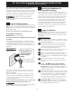
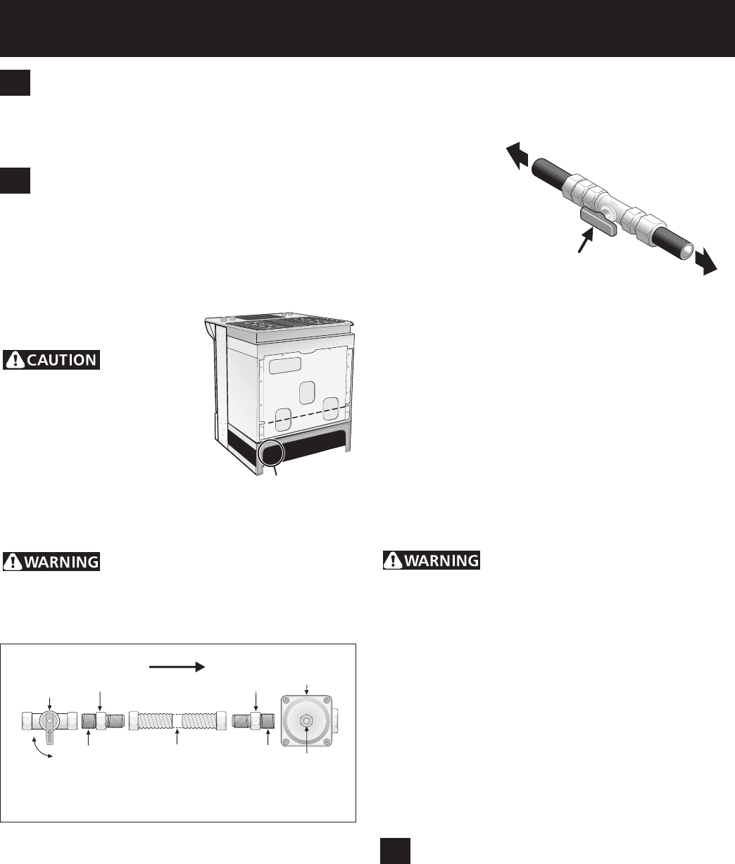
Figure 5
Shutoff Valve -
Open position
to appliance
to gas supply line
All connections must be wrench-tightened
Figure 4
Flare
Union
Flare
Union
GAS FLOW
Manual
Shutoff
Valve
Pressure
Regulator
On
Off
Flexible
Connector
Access
Cap
Nipple Nipple
Connection to Pressure Regulator
The regulator is already installed on the appliance.
Do not make the connection too tight.
The regulator is die cast. Overtightening may crack the
regulator resulting in a gas leak and possible fire or
explosion.
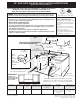
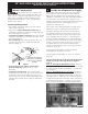
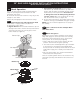
Figure 3
Your regulator is in location
shown below.
Do not
allow regulator to rotate
on pipe when tightening
fittings.
PRESSURE REGULATOR
LOCATION
3
Seal the openings
Seal any openings in the wall behind the range and
in the floor under the range after gas supply line is
installed.
4
Connect the range to the gas
supply
Important: Remove all packing material and literature
from range before connecting gas and electrical supply.
To prevent leaks, put pipe joint sealant on all external
pipe threads.
Use pipe-joint compound made for use with Natural and
LP/Propane gas to seal all gas connections. If flexible
connectors are used, be certain connectors are not
kinked.