BM125M92RB 02227_PL_LT_CRD Instruction manual Manuel d’instructions Manuale di istruzioni Please read these instructions carefully and make sure you understand them before using this machine. Merci de lire trés attentivement le manuel d'instructions. Assurez-vous d'avoir tout compris avant d'utiliser ce tracteur. Prima di utilizzare la macchina leggete queste istruzioni con attenzione ed accertatevi di averle comprese bene.
1 Safety rules. Sicherheitsvorschriften. Règles de sécurité. Reglas de seguridad. Norme antinfortunistiche. Veiligheidsregels. 2 Assembly. Zusammenbau. Montage. Montaje. Montaggio. Montering. 18 3 Functional description. Funktionsbeschreibung. Description du fonctionnement. Descripción del funcionamiento. Funzionamento. Beschrijving van functies. 37 4 Before starting. Maßnahmen vor dem Anlassen. Avant de démarrer. Antes del arranque. Prima dell’avviamento. Maatregelen vóór het starten.
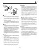
1. Safety Rules Safe Operation Practices for Ride-On Mowers IMPORTANT: THIS CUTTING MACHINE IS CAPABLE OF AMPUTATING HANDS AND FEET AND THROWING OBJECTS. FAILURE TO OBSERVE THE FOLLOWING SAFETY INSTRUCTIONS COULD RESULT IN SERIOUS INJURY OR DEATH. I. Training • • Read the instructions carefully. Be familiar with the controls and the proper use of the equipment. • Never allow children or people unfamiliar with the instructions to use the lawnmower. Local regulations may restrict the age of the operator.
IV. Maintenance and Storage • Keep all nuts, bolts and screws tight to be sure the equipment is in safe working condition. • Never store the equipment with petrol in the tank inside a building where fumes may reach an open flame or spark. • Allow the engine to cool before storing in any enclosure. • To reduce the fire hazard, keep the engine, silencer, battery compartment and petrol storage area free of grass, leaves, or excessive grease. • Check the grass catcher frequently for wear or deterioration.
• • • - nadat u een ongewenst voorwerp heeft geraakt. Inspecteer de maaimachine op schade en voer reparaties uit voordat u de machine weer start en gebruikt; - als de machine abnormaal begint te trillen (onmiddellijk controleren). - vor dem Entfernen von Verstopfungen aus dem Mähwerk oder dem Auswurf; Schakel de aandrijving naar de hulpstukken uit tijdens transport of als ze niet worden gebruikt.
These symbols may appear on your machine or in the literature supplied with the product. Learn and understand their meaning. Diese Symbole finden Sie auf Ihrer Maschine oder in Unterlagen, die mit dem Produkt ausgehändigt wurden. Bitte machen Sie sich mit deren Bedeutung vertraut. Ces symboles peuvent figurer sur tracteur ou dans les publications fournies avec le produit. Apprenez à comprendre la signification de ces symboles.
These symbols may appear on your machine or in the literature supplied with the product. Learn and understand their meaning. Diese Symbole finden Sie auf Ihrer Maschine oder in Unterlagen, die mit dem Produkt ausgehändigt wurden. Bitte machen Sie sich mit deren Bedeutung vertraut. Ces symboles peuvent se montrer sur votre machine ou dans les publications fournies avec le produit. Apprenez à comprendre la signification de ces symboles.
01738 GEFAHR AUGEN SCHÜTZEN EXPLOSIVE GASE KÖNNEN ERBLINDUNG UND KÖRPERVERLETZUNGEN VERURSACHEN. ZU VERMEIDEN: • FUNKEN • FEUER • RAUCHEN SCHWEFELSÄURE KANN ERBLINDUNG ODER SCHWERE VERÄTZUNGEN VERURSACHEN. AUGEN UNVERZÜGLICH MIT WASSER AUSSPÜLEN. SOFORT ÄRZTLICHE HILFE AUFSUCHEN. GEVAAR OGEN BESCHERMEN EXPLOSIEVE GASSEN KUNNEN BLINDHEID OF LETSEL VEROORZAKEN. GEEN • VONKEN • VUUR • ROKEN ZWAVELZUUR KAN BLINDHEID OF ERNSTIGE BRANDWONDEN VER-OORZAKEN. OGEN ONMIDDELLIJK MET WATER SPOELEN.
2. Assembly. 2. Zusammenbau. 2. Montage. 2. Montaje 2. Montaggio. 2. Montering. Before the tractor can be used certain parts must be assembled, which for transportation reasons are enclosed in the packing. Antes de poder utilizar el tractor, hay que montar algunas piezas que, por razones de transporte, van empaquetadas en el embalaje. Vor der Anwendung des Aufsitzmähers müssen gewisse Teile eingebaut werden, die aus Transportgründen in der Verpack-ung lose beigefügt sind.
2 Asiento Remueva la manilla de ajuste y la arandela plana que aseguran el asiento al empaque de cartón y póngalos de lado para poder utilizarlos durante la instalación del asiento sobre el tractor. Gire el asiento hacia arriba y remuevalo del embalaje de cartón. Remueva y desechese del embalaje de cartón. Colocar el asiento y en el asiento del recipiente de manera que la cabeza del bulón de la espalda esté posicionada en el agujero ancho ranurado en el recipiente.
2 NOTE! Check that the flex is correctly connected to the safety switch (3) on the seat holder. HINWEIS! Prüfen, daß das Kabel richtig an dem Sicherheitsschalter (3) auf dem Halter des Sitzes angeschlossen ist. REMARQUE: Vérifier que le câble électrique est bien connecté sur le contacteur de sécurité (3) placé sous l'embase du siège. NOTA! 3 Controlar que el cable está correctamente acoplado al interruptor de seguridad (3) en el soporte del asiento.
2 1. 2. 3. 4. 5. 6. Battery Cover Cable Positive (+) Cable Negative (-) Fender Battery terminal Battery 1. 2. 3. 4. 5. 6. 1. 2. 3. 4. 5. 6. Batterieabdeckung Positives Kabel (+) Negatives Kabel (-) Schutzblech Batterieklemme Batterie 1. Coperchio dellí accumulatore 2. Cavo elettrico positivo (+) 3. Cavo elettrico negativo (-) 4. Paraurti 5. Polo della batteria 6. Batteria 1. Capotage de batterie 2. Câble (+) 3. Câble (-) 4. Carrosserie 5. Borne de la batterie 6. Batterie 1. 2. 3. 4. 5. 6.
2 WARNING: Positive terminal must be connected first to prevent sparks from accidental grounding. Remove terminal caps and discard. Connect the red cable to + and then the black earth cable to -. Screw tight the cables. Grease the battery poles with vaseline to prevent corrosion. Replace battery cover. WARNUNG! Um einen Kurzschluß zu vermeiden, muß der Pluspol zuerst angeschlossen werden. Die Schutzkappen von den Anschlußklemmen entfernen und entsorgen. Die Batterie in Position neben den Fahrersitz bringen.
2 024 71 TO ADJUST GAUGE WHEELS PARA AJUSTAR LAS RUEDAS CALIBRADORAS Gauge wheels are properly adjusted when they are slightly off the ground when mower is at the desired cutting height in operating position. Gauge wheels then keep the deck in proper position to help prevent scalping in most terrain conditions. • Adjust gauge wheels with tractor on a flat level surface. • Adjust mower to desired cutting height.
2 2 To install bagger components to tractor 1 1. 2. 3. 4. 5. 2 1. Discharge Chute 2. 3/8 Nut 3. Flat Washer 02 2 4 Support Bracket Clevis Pin 10 x 17mm 1 Retainer Spring Clevis Pin 10 x 50mm 10,3mm (13/32") flat washer 5 3 3 1 02 81 3 77 3 • • • Remove discharge chute from rear of tractor. Unhook the two (2) straps and pull chute out and away from tractor. Remove the two (2) 3/8 nuts and flat washers from the bolts at the tractor back plate.
2 1 2 To Assemble Bagger NOTE: For ease of assembly, you may wish to obtain the assistance of another person when putting the bagger together. • Holes in front bagger tube are at an angle. Place front bagger tube against lower bagger tube and check for proper hole alignment before assembling bolts. • Assemble front and lower bagger tubes using four (4) 1/4 x 50,8mm carriage bolts and lock nuts supplied. Tighten securely. • Slide front and lower bagger tube assembly into the bagger assemby.
2 1 2 A 3 A 4 21 02 4 1. 2. 3. 4. Handle Retainer Spring Pin Plug 1. 2. 3. 4. Mango Resorte fijador Clavija Tapon o tapa 1. 2. 3. 4. Handgriff Fixierfeder Stift Stöpsel 1. 2. 3. 4. Impugnatura Coppiglia Perno Kit Mulching 1. 2. 3. 4. Poignée de l'insert Epingle Axe de fixation Tête de l'insert 1. 2. 3. 4. Hendel Sluitveer Pen Plug To assemble and install mulcher plug • • • Para ensamblar y montar la tapa mulching Remove spring retainer and pin from handle. Insert plug into handle.
3. Functional description. 3. Funktionsbeschreibung. 3. Description du fonctionnement. 3. Descripción del funcionamiento. 3. Funzionamento. 3. Beschrijving van functies 1 7 5 9 6 3 2 8 4 Anordnung der Bedienungseinrichtungen 1. Lichtschalter 2. Gashebel 3. Brems- und Kupplungspedal 4. Schalthebel 5. Ein- und Ausschalten des Mähaggregats 6. Schnelles Heben und Senken des Mähaggregats 7. Zündschloß 8. Feststellbremse 9. Kalstartregler Positioning of controls 1. Light switch position 2.
3 1 7 5 9 6 3 2 8 4 02631 Emplacement des commandes 1. Interrupteur des phares 2. Commande des gaz (Accélérateur) 3. Pédale d'embrayage et de frein 4. Levier de commande de la boîte de vitesses 5. Embrayage/débrayage du carter de coupe 6. Relevage et abaissement du carter de coupe 7. Clé de contact/démarrage 8. Frein de parking. 9. Starter Comandi 1. Interruttore luci 2. Acceleratore 3. Pedale freno/frizione 4. Leva del cambio 5. Inserimento/disinserimento del dispositivo di taglio. 6.
3 1. Light switch position 1. Lichtschalter 1. Interrupteur des phares 1. Interruptor de alumbrado 1. Interruttore luci 02309 1. Schakelaar verlichting 2. Throttle control The throttle control regulates the engine revs and thus the rotation speed of the blades. = Full speed = Idling speed 2. Gashebel Mit dem Gashebel wird die Drehzahl des Motors und damit die Drehgeschwindigkeit des Mähaggregats geregelt. = Vollgas = Leerlauf 2.
3 3. Pedal de freno y de embrague Al apretarlo se frena el vehículo y al mismo tiempo se desa copla el motor deteniéndose la propulsión. 02 3. Pedale freno/frizione 47 3 01 Premendo il pedale il trattore si frena, il motore va in folle e cessa la trazione. 35 8 3. Rem- en koppelingspedaal Als de pedaal ingedrukt wordt, remt het voertuig. Tegelijkertijd wordt de motor ontkoppeld en stopt de aandrijving. 3.
3 5. Commande d'embrayage et de débrayage du carter de coupe Pousser le levier vers l'avant et le verrouiller pour embrayer le carter de coupe. Les courroies d'entraînement seront alors en tension et les lames commenceront à tourner. Ramener le levier vers l'arrière pour débrayer le carter de coupe, les lames seront alors freinées par le frottement des patins de frein sur les poulies d'entraînement. 02 47 3 02442 5.
3 01949 OFF ON START 7. Cerradura de encendido 7. Ignition Lock La llave de encendido puede hallarse en tres posiciones diferentes: OFF Corriente eléctrica cortada ON Corriente eléctrica conectada START Motor de arranque acoplado ADVERTENCIA! Si abandona la máquina sin vigilancia, no deje nunca la llave en la cerradura. There are three different positions for the ignition key: OFF All electric current broken. ON Electric current connected. START Start motor connected.
3 8. Frein de stationnement 01 3 47 35 8 02 02 Pour enclencher le frein de stationnement : 1. Enfoncer à fond la pédale d'embrayage/frein. 2. Relever vers le haut le levier du frein de stationnement et le maintenir dans cette position. 3. Relâcher la pédale d'embrayage/frein. Relâcher le levier du frein de stationnement qui restera dans sa position verrouillée (en haut).
4. Before starting. 4. Maßnahmen vor dem Anlassen. 4. Avant de démarrer. 4. Antes del arranque. 4. Prima dell’avviamento. 4. Maatregelen vóór het starten. Reposición de combustible Filling up The engine should be run of pure (not oil mixed) unleaded petrol. Do not fill beyond the lower edge of the filling hole. Do not fill over max level. El motor ha de funcionar con gasolina pura (sin mezcia de aceite), sin plomo. El nivel no ha de sobrepasar el borde inferior del orificio de llenado.
4 The oil level should lie between the two markings on the oil stick. If more oil is needed add SAE 30 oil to the “FULL” marking. SAE 5W-30 oil should be used during the winter (below freezing point). Der Ölstand soll zwischen den beiden Marken auf dem Meßstab liegen. Wenn dies nicht der Fall ist, Motoröl SAE 30 bis zur Marke ”FULL” einfüllen. Im Winter (bei Frostgefahr) ist Motoröl SAE 5W-30 anzuwenden.
5. Driving. 5. Betrieb. 5. Conduite. 5. Conducción. 5. Guida. 5. Rijden. Démarrage du moteur S'assurer préalablement que le carter de coupe est en position de transport (c'est à dire : relevé au maximum) et que le levier d'embrayage et de débrayage du carter de coupe est en position "débrayée" (voir figure).
5 Bei warmem Motor: Gashebel in die Vollgasstellung " schieben. " Si le moteur est chaud : pousser la commande des gaz à mi-distance de sa position d'accélération maximale. " ". Moter caliente: Empuje el acelerador hasta la mitad de su recorrido hacia la posición de plenos gases " ". Motore caldo: Portare il comando del gas sul massimo " ". Bij een warme motor: Schuif de gashendel halverwege naar de volgaspositie " ". Warm motor: Push the gas control half-way to full gass position " ".
5 NOTE! NOTA! The machine is equipped with a safety switch which immediately breaks the current to the engine if the driver leaves the seat with engine running and with the connection/disconnection lever in position “connection”.Your machine is also equipped with a system that will not allow mower to operate if the bagger or optional rear discharge deflector is not installed properly.
5 Cutting tips • • • • • • • Conseils pour la tonte Clear the lawn from stones and other objects which can be thrown away by the blades. Localize and mark stones and other fixed objects to avoid collision. Begin with a high cutting height and reduce until the required cutting result is obtained. The cutting result is best with high engine speed (blades rotate quickly) and low gear (machine goes slowly).
5 Pour vider le bac: Votre tracteur est équipé d'une alarme sonore qui vous avertit lorsque le bac est plein. Pour arrêter l'alarme, débrayer les lames. • Amener le tracteur là ou vous souhaitez le décharger. • Mettre le levier de boîte de vitesses au point mort et tirer le frein à main. • Tirer le leiver de vidange du bac vers le haut puis vers l'avant afin d'ouvrir le bac et vider l'herbe coupée. • Remettre ensuite le levier dans sa position initiale.
5 To convert mower • (Converting to mulching or rear discharging will require the purchase of these accessories.) • To mulching Place deck into the high cut position. Remove bagger or optional rear discharge deflector. Unhook the two (2) straps and remove discharge chute. Insert plug and handle assembly through back plate and onto the mower deck chute adaptor. • Retain the plug assembly by connecting the two straps over the handle and hook into the holes provided.
5 ATTENTION! • • • Ne jamais utiliser un tracteur sur des pentes excédant 10°. Les risques de renversement étant alors très importants. Ne jamais rouler parallèlement à la pente du fait des risques de renversement. Toujours rouler perpendiculairement à la pente, aussi bien en montant, qu'en descendant. Ne jamais arrêter ou démarrer un tracteur en pente. ADVERTENCIA! • • • WARNING! • • • PERICOLO! Do not drive in terrain at an angle of more than max. 10°. The risk for spark-over backwards is large.
5 Switching off the engine Disconnect the cutting unit by moving the connect/disconnect lever downwards. Move the gas control to “ ”. Lift up the cutting unit and turn the ignition key to “STOP” position. Abstellen des Motors Mähaggregat durch Abwärtsführen des Aggregatschalthebels auskuppeln. Gashebel nach unten auf “ ” führen. Mähaggregat anheben und den Zündschlüssel auf “STOP” drehen. Arrêt du moteur Débrayer les lames en abaissant le levier de commande d'embrayage des lames.
6. Maintenance, adjustment. 6. Wartung (Instandhaltung), Einstellung. 6. Entretien, réglages. 6. Mantenimiento, ajuste. 6. Manutenzione. 6. Onderhoud, afstelling. WARNING! ADVERTENCIA! Before servicing the engine or cutting unit the following shall be carried out: • Press down the clutch/brake pedal and engage the parking brake lever. • Put gear lever in neutral. • Move connection/disconnection lever to disengaged position. • Switch off engine. • Remove the ignition cable from the plug.
6 Engine hood • • • • 1 • Raise hood. Unsnap headlight wire connector. Stand in front of tractor. Grasp hood at sides, tilt forward and lift off of tractor. To reinstall, slide hood pivot brackets into slots in frame. Reconnect headlight wire connector and close hood. Motorhaube • • • • 01536 02 47 3 • Motorhaube hochklappen. Scheinwerferanschluß lösen. Vor den Mäher treten. Motorhaube an den Seiten anfassen, nach vorn kippen und aus dem Mäher herausheben.
6 Maintenance Mantenimiento NOTE: Periodic maintenance should be performed on a regular basis in order to keep your tractor in good running condition. WARNING: Disconnect spark plug wire to prevent accidental starting before attempting any repair, inspection, or maintenance. Before each use: • Check oil, lubricate pivot points as necessary. • Check to see all bolts, nuts, and cotter pins are in place and secure. • Check the battery, terminals and vents. • Recharge slowly at 6 amperes if needed.
6 Pour assurer l'entretien du moteur Se référer au manuel d'utilisation du moteur. Vidange de l'huile du moteur Retirer le bouchon (1) et placer le tuyau de vidange (2). Pour ouvrir la soupape de vidange, repousser légèrement la soupape en la faisant tourner dans le sens contraire des aiguilles d'une montre pour sortir du cran, puis tirer sur la soupape pour libérer l'huile.
6 SERVICE RECORD Fill in dates as you complete regular service As Needed Every 8 hours Every 25 hours Change engine oil (without oil filter) ................................................... Every. 50 hours • Change engine oil (with oil filter) ............................................................................ Lubricate pivot points ......................................................................... Check brake operation ................................ • Clean air screen .........
6 Blades Lames: The blades should be sharp to achieve best cutting results. Sharpening can be carried out with a file or grinding disc. NOTE: It is very important that both blades are sharpened equally to avoid imbalance. Les lames doivent être parfaitement affûtés pour obtenir une belle coupe. L'affûtage peut être réalisé à l'aide d'une lime ou d'une meule. REMARQUE: Il est très important d'affûter les deux extrémités de la lame de façon identique afin d'éviter tout déséquilibrage.
6 8 7 5 Star pattern blade The center of this blade has a five (5) star pattern. The bolt that attaches this blade has normal Right Hand threads that loosens by turning ( ) counter-clockwise and tightens by turning ( ) clockwise. LH 3 6 1 5 2 Messerbalkenbohrung mit fünfeckige Aussparung 4 1. Hex bolt right hand threaded. 2. Lock Washer 3. Flat Washer 4. Blade 5. 6. 7. 8. 1. Sechskantschraube mit Rechtsgewinde 2. Federscheibe 3. Flache Unterlegscheibe 4. Schneidmesser 5.
6 For best results mower blades must be kept sharp. Replace bent or damaged blades. BLADE REMOVAL • Raise mower to highest position to allow access to blades. • Remove hex bolt, lock washer and flat washer securing blade. • Install new or resharpened blade with trailing edge up towards deck as shown. IMPORTANT: To ensure proper assembly, center hole in blade must align with star on mandrel assembly. • Reassemble hex bolt, lock washer and flat washer in exact order as shown.
6 38mm Brakes The brakes are located inside the right rear wheel. The wheel should be dismantled for best access. • Press down the clutch/brake pedal and engage the parking brake. 2 Bremse 1 Die Bremse sitzt innerhalb des rechten Hinterrades. Für beste Zugänglichkeit ist das Rad auszubauen. • Kupplungs-/Bremspedal durchtreten und die Feststellbremse einschalten. 02200 CRD 1. Measure the distance between the brake lever and the adjuster nut. 2. The distance should be 38mm (1.5"). 3.
6 Desmontaje de la unidad de corte 2 Trabajar desde el lado derecho de la máquina. 1. Quitar después la correa de la polea del motor (1). 2. Quitar los dos resortes posteriores (2) y golpear con un martillo los muñones de eje hasta sacarlos. 3. Quitar los resortes (3), (4), (5) y los ejes respectivos. 4. Tirar hacia atrás de la palanca para la elevación y descenso de la unidad de corte. 5. Extraer la unidad de corte de la máquina.
6 Remplacement de la courroie d'entraînement du carter de coupe 1. Déposer le carter de coupe (voir chapitre précédent). 2. Sortir la courroie d'entraînement des gorges de poulie en commençant par la poulie du côté gauche du carter de coupe, puis par les autres poulies. 3. Retirer ensuite entièrement la courroie du carter de coupe. 4. Pour la mise en place de la nouvelle courroie, procéder dans l'ordre inverse. Vérifier que la courroie est correctement positionnée devant tous les guides de courroie.
6 A 1 2 01268 01156 B Adjustment of the cutting unit 1. 2. 3. 4. A. In the direction of travel Check that the air pressure is correct in all four tires. Make sure that the machine is on a horizontal surface. Lift up the cutting unit to its highest position. Measure the distances A and B. To achieve best cutting results the cutting unit’s front edge (B) should be about 10 mm (0.375") lower than the back edge (A). Adjust in the following way to raise the back edge: 1.
6 REGLAGE TRANSVERSAL 00598 1 • • Relever le carter de coupe au maximum. A partir du milieu de chaque extrémités latérales du carter de coupe, mesurer la distance du bord du carter par rapport au sol . • La distance (A) doit être la même des deux côtés à 6 mm près. • Si un réglage est nécessaire, ne l'effectuer que d'un seul côté en se référant à l'autre côté. • Abaisser ou soulever un côté du carter de coupe en ajustant la position de l'écrou de réglage de ce côté.
6 Cambio de correa propulsora 1. Desmontar el equipo de corte del tractor. 2. Desmontar el limitador de movimientos del acoplamiento (1). 3. Aplicar el freno de estacionamiento y tirar hacia arriba de la correa para sacarla de la rueda libre (2), de la acoplamiento (3). 4. Introducir la correa entre dos aspas del ventilador y hacer girar éste a izquierdas hasta que queda libre la correa (4). 5. Quitar después la correa de la polea del motor (5). 5 2 Sostituzione della cinghia di trazione 3 1.
6 1 EINSTELLUNG DES SCHALTHEBELS DES DIFFERENTIALGETRIEBES 02239 Das Differentialgetriebe muß sich in Leerlaufstellung befinden, wenn der Schalthebel in der Neutral-Stellung (N) (Verschlußsperre) steht. Diese Einstellung wird bereits vom Hersteller im Werk durchgeführt. Sollte es jedoch dennoch erforderlich sein, weitere Einstellungen vorzunehmen, so muß folgendermaßen vorgegangen werden: • Zunächst muß sichergestellt werden, daß sich das Differentialgetriebe in Leerlaufstellung (N) befindet.
7. Troubleshooting. 7. Störungssuche. Motor springt nicht an Engine will not start 1. 2. 3. 4. 1. 2. 3. 4. No fuel in fuel tank. Plug defective. Plug connection defective. Dirt in carburetor or fuel pipe. Anlasser dreht den Motor nicht durch Start motor will not turn engine 1. 2. 3. 4. 5. 6. 7. 1. 2. 3. 4. 5. 6. 7. Battery flat. Poor contact between cable and battery pole. Connection/disconnection level in wrong position. Main fuse defective. Ignition lock defective.
8. Storage. 8. Aufbewahrung. 8. Remisage. 8. Conservación. The following steps should be taken when mowing season is over: • Clean the entire machine, especially underneath the cutting unit cover. Do not use high pressure washer for cleaning. Water can enter engine and transmission and shorten the useful life of the machine. • Touch up all chipped paint surfaces in order to avoid corrosion. • Change engine oil. • Drain the fuel tank. Start the engine and allow it to run until it is out of fuel.
DECLARATION OF CONFORMITY • The Manufacturer: Electrolux Home Products, 172 Old Elloree Road, Orangeburg, SC 29115, USA DECLARACIÓN DE CONFORMIDAD • El Fabricante: Electrolux Home Products, 172 Old Elloree Road, Orangeburg, SC 29115, USA Herby declares that the machinery described below; • Category......................Rotary Mower • Guaranteed Sound Power • Make.................................. Bestgreen Level ................................. 100 dB (A) • Type ...........................