Operating and installation manual Hydro-extractor C240 / C240R C260 / C260R C290R 487 22 52 01/EN 08.
Hydro-extractors C240/C240R, C260/C260R, C290R List of contents: Instruction for use: General, safety . . . . . . . . . . . . . . . . . . . . . . . . . . . . . . . . . . . . . . . . . . . . . Procedure for use . . . . . . . . . . . . . . . . . . . . . . . . . . . . . . . . . . . . . . . . . . . Maintenance . . . . . . . . . . . . . . . . . . . . . . . . . . . . . . . . . . . . . . . . . . . . . . . 5 6 7 Installation: Unpacking, open the lid, come with all types . . . . . . . . . . . . . . . . . . . . . .
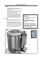
Instructions for use General The hydro-extractor is an invaluable complement to a washing machine and other drying equipment: It complements the washing machine by very efficient dewatering of the laundry after the wash programme is completed. It complements the tumble dryer or drying cabinet by considerably reducing the drying time. Drying of clothes is energy-intensive and an efficient hydro-extractor can save considerable amounts of energy every year.
Instructions for use 6 Procedure for use 1 Preparation 1 Place the load in an even layer all around the drum Place long articles in a zig-zag fashion so that they are not stretched unnecessarily while being extracted. Place heavy items at the bottom and light items at the top. Check that items do not hang over the edge of the extractors drum. Finish by placing a towel or similar at the top. Be sure to keep the towel within the edge of the drum.
Instructions for use Maintenance The below-mentioned intervals for maintenance apply in situations of normal use, e.g. a tenancy estate laundry. If the machine is used professionally, e.g. in a laundrette, this interval should be halved. Every 14 days It is important to carry out regular checks of the hydro extractor's function, particularly for personal safty reasons.
Installation 8 Installation of hydro-extractor: 1 With freely suspended basket Unpacking 1 The hydro-extractor is protected against transport damage and bolted to a pallet before delivery. The transport protection consists of a wooden plug fitted between the pallet and the counterweight of the motor. Through the pallet and the wooden plug, a bolt has been entered to reach into the counterweight.
Installation 9 Installation of all types of hydro-extractor Positioning 1 1 Minst 250 mm The extractor is to be placed as close to a floor drain or gutter as possible. The distance to the wall or other equipment must be at least 250 mm. The distance on the left side must be at least 250 mm. To facilitate servicing, it is recommended to leave a space of min. one metre behind the machine. Drain 2 Fit the rubber hose. Dimension of the drain pipe: hose Ø75 mm.
Installation 10 Installation of all types of hydro-extractor Quality requirements concerning the base The base must be very stable in order to absorb the dynamic forces transferred in the spinning process. Normally, the hydro-extractor can be attached by means of expansion bolts (size M12) directly into a concrete floor of good quality and adequate thickness - see bolt height B in the table below; or the enclosed foundation bolts can be cast into the floor, see procedure next page.
Installation 11 Installation of all types of hydro-extractor Concreting, procedure: 1 • Cut out the floor approx. 75 mm down. Make sure that the sides of the hole have an outwards slope; the lower longitudinal dimension L must be 120 mm bigger than the dimension at the edge of the floor. Build up a casting mould, see fig. 1. • Water the hole thoroughly and apply cement plaster to the bottom and sides of the hole. • Concrete the foundation. Foundation bolts can be concreted into the foundation.
Installation 12 Attachment of hydro-extractor with freely suspended basket C When using expander bolts use size M12. B Bottom ring Drill holes in the floor. The depth and diameter must fit the expander bolts used. To position holes correctly you can use the template which is supplied. The extractor bottom plate can also be used as a template. Place the expander bolts in the holes. 2 mm Fitting of hydro-extractor Position the hydro-extractor and adjust it to make it completely horizontal.
Installation Attachment of hydro-extractor with rigidly suspended basket 13 C240/C240R Position the hydro-extractor. Adjust the extractor to make it completely horizontal. Use gaskets made of stainless or galvanised metal plate to place under the feet of the machine. The gaskets must be big enough to cover the entire surface of the foot. Fit the square gaskets and nuts. NB! Check the nuts and tighten them when the hydro-extractor has been in use for a few months.
Installation 14 Technical data for hydro-extractors with 50 Hz and 60 Hz mains frequency Free Free suspension suspension C260 C240 Drum suspension Basket volume in litres Basket Capacity [kg] (Dry garments) 8 Basket Speed [rpm] 50 Hz 1450 60 Hz 1740 Basket G-factor [kp/kg] 50 Hz 440 60 Hz 635 Power consumption per spin [kWh] 0.04 Max. Floor load per spin (50 Hz) [kN] 1.
Installation 15 Electrical installation. Electrical Installation is to be carried out by an authorized electrician. Switch Fit a current switch prior to the extractor. The cable between switch and hydro-extractor must comply with at least HO5VV-F in accordance with CEE(13)53 and must hang in a loop. Fuse Fit a current switch prior to the extractor. Connect the extractor to a separate fuse board. The motor is fitted with a thermal fuse, which is why separate motor protection is unnecessary.
Installation 16 1 Voltage change Voltage change must be done by authorized personnel. A (Y) Some extractors have a dual voltage facility and can be changed over in connection with installation. An extractor, which upon delivery is connected for 400-415 V 3 AC (Y-connection), can be changed over to 230 V 3 AC (∆-connection) and vice versa. The change is done in the control unit.
Installation Printed circuit board for coin connection. 1 A: Screw terminal for coinpayment unit. B1: Screw-terminal for CP C1: Switch for setting number of coins. D: Jumper with joiner. 17 1 C1 D B1 E: Switch for time sitting. E A Connection 2 2 The cables from the coin reader are connected to the screw-terminal (A) on the hydro-extractor printed circuit board. a = red b = blue c = yellow a 3 3 Check that the jumpers (D) are not short-circuited (the joiner is movable).
Installation 18 Setting the number of coins 4 The number of coins that the hydroextractor is selected by setting switch 1+2+3 (C) No. of coins 4 OFF 1 ON C Connection to central panel (CP) CALCAD 1 • Disconnect the power to the hydro-extractor. • The right polarity is important: ± 24Vto ± 24V and 0 to 0.
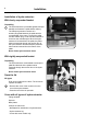
Installation Test run 19 1 When the installation work has been completed, a functional check must be carried out as follows: 1. Make sure that the main switch is in OFF position and that the drum is empty. Close the lid. 2. Turn the main switch ON. The green lamp for - button must now flash. Press the button to open the lid.
Washer extractors, Tumble dryers, Hydro extractors Types: W.55H., W3..., WN3..., W4.H., EXSM.X., H1..., N1130.., N1190.., N2..., N3..., N4..., N5... Product standards: EN 60335-2-4, -7, -11 EMF standards: EN 50366:2003 + A1 EMC standards: EN 61000-6-1 (2001) W.55H., W3..., W4.H., N1130, N1190, N2..., N3... EN 61000-6-3 (2001) W.55H., W3..., WN3..., W4.H., EXSM.X., N1130, N1190, N2..., N3... A11 (2003) WN3..., N5... EN 61000-3-11 (2001) EXSM.X. EN 61000-6-2 (2005) WN3..., N4..., N5... EN 61000-6-3 (2007) N4.
Skrotning av maskin När maskinen inte längre skall användas måste den lämnas till en återvinningsstation för destruktion. Många detaljer i maskinen går att återanvända, men den innehåller även annat material som måste tas om hand på ett korrekt sätt. Lämna därför aldrig maskinen eller delar av maskinen i hushållsavfallet, eftersom det kan leda till hälsorisker eller skador på miljön. Scrapping of machine When the machine is no longer to be used, it must be submitted to a recycling facility for destruction.
www.electrolux.com/laundrysystems Share more of our thinking at www.electrolux.