
Installation manual


Installation
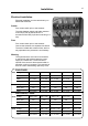
17
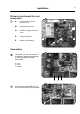
Printed circuit board for coin
connection.
A: Screw terminal for coin-
payment unit.
B1: Screw-terminal for CP
C1: Switch for setting number of
coins.
D: Jumper with joiner.
E: Switch for time sitting.
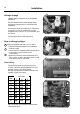
Connection
The cables from the coin reader are
connected to the screw-terminal (A)
on the hydro-extractor printed
circuit board.
a = red
b = blue
c = yellow
Check that the jumpers (D) are not
short-circuited (the joiner is movable).
1
1
B1
E
C1
A
D
2
3
a
b c
2
D
3