
Service manual


12. Functions sequences
12
Service
manual
487 03 29 91
12.4
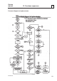
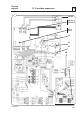
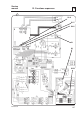
Circuit diagram 489 50 01 77 has been used in describing the function sequence in this
section: This diagram is in principle identical to all the other circuit diagrams since the
control voltage is 24 V AC 50/60 Hz.
Start of extraction
The machine starts extraction when the operator presses the START button on the
control panel.
Drive motor M1 is energised via connection X3-X5 (star connection) or X2-X7(delta
connection) when relay K1 operates. For K1 to operate, the following conditions must be
fulfilled:
• The lid´s Reed element R1-R2 must be activated, e.g. the lid closed (this does not
apply to the C290R, which has no Reed element in the lid).
• The mechanical lid switch (SW1) must be activated (lid Closed).
When the lid´s Reed element closes, a signal (GND potential) is obtained at terminal
OUT1 S3 on connection S3. This signal is supplied via the circuit board to terminal
GND2 on connection S6. Terminal OUT2 on S6 will have GND, potential, which
allows the extractor to start.The logic circuit will now supply control voltage to terminal
S1:4, which via an interlock contact on brake relay K2 supplies one side of relay coil
K1. The other side of the relay coil receives voltage from S1:2 via lid switch SW1 and
the motor´s internal thermal protection F3.
When K1 operates, an interlock contact in the control circuit opens to relay K2 (brake
relay), thereby preventing K2 from operating at the same time as K1.
3