FREESTANDING ELECTRIC RANGE PRODUCT SERVICE MANUAL EI30EF55G , * ,, CEI30EF5G * * * MODELS - EW30EF65G CEW30EF6G Wave-Touch™ IQ Touch™ EW30EF65 Publication # 5995521555 August 2008 EI30EF565 PN / 316439223
TABLE OF CONTENTS SAFE SERVICING PRACTICES............................... 3 SERVICE TIPS - DEVELOP GOOD WORK HABITS.......................................................... 4 SERVICE TOOLS AND EQUIPMENT....................... 4 RANGE TECHNICAL DATA.................................5-14 Maximum Allowable Surface Temperatures........................................... 5 RTD Temperature / Resistance Chart................... 5 Electric Range Component Resistance Chart............................................
SAFE SERVICING PRACTICES - ALL APPLIANCES To avoid personal injury and/or property damage, it is important that Safe Servicing Practices be observed. The following are some limited examples of safe practices: 1. DO NOT attempt a product repair if you have any doubts as to your ability to complete it in a safe and satisfactory manner. 2. Before servicing or moving an appliance: • Remove the power cord from the electrical outlet, trip the circuit breaker to the OFF position, or remove the fuse.
SERVICE TIPS - DEVELOP GOOD WORK HABITS Consistently following a standard routine when servicing appliances will insure that you do not waste time searching for a complex solution to a simple problem. One of the most common mistakes made by service technicians is failing to verify the incoming power supply to the appliance. Many times electronic controls and other components are replaced unnecessarily because the incoming power supply was not verified.
RANGETECHNICAL TECHNICAL DATA RANGE DATA Maximum Allowable Surface Temperatures All gas and electric ranges must comply with U.L and A.N.S.I. surface temperature limits outlined in the following chart. Note that the testing temperature is different for electric ranges produced after 08/26/2003.
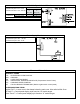
RANGE TECHNICAL DATA ES 610/615 Oven Relay Board Circuit Analysis Matrix Relay Contacts P4 (R) to P2 (O) P6 (BK) to P10 (Y) P6 (BK) to P8 (BL) P6 (BK) to P12 (Y/BK) J4/3 (BK) to J4/5 (V) J4/3 (BK) to J4/6 (BR) Component L2 Out Relay Bake Element Broil Element Lower Oven Element Convection Element Door Lock Motor X X X X Bake / Time Bake Convection Bake/Roast O P E R A T I O N P X X Broil Dehydrate X X X X X X X X Bread Proof Slow Cook Keep Warm (Upper Oven) X X Keep Warm (Lower Ov
VSC Test Points. Connector P6 pins 1 & 6 - 5 vdc Connector P2 Pins 3 & 5 - 120 vac OPERATION Variable Speed Control Board RELAY CONTACTS P2/5 (BK) to P2/1 (Tan) Oven Lamps P2/5 (BK) to P2/7 (Pink) X Convection Fan Mtr. X X = Contact Closed NOTE: All voltages are approximate. Power Supply Board Power Supply Board (PS1 or PS2) Test Points Connector P1 pins 1 & 4 - 120 vac Connector P2 pins 1 & 5 - 8 vdc NOTE: All voltages are approximate.
RANGE TECHNICAL DATA ELECTRONIC OVEN CONTROL FAILURE/FAULT CODES (ES630) For each Fault code there is a listing of the likely failure condition or cause, as well as suggested corrective actions to be taken. Perform the steps one at a time in the order listed below to correct the specific failure condition. Note: Fault codes are not a foolproof system. Never assume that a part has failed based on a displayed fault code.
RANGE TECHNICAL DATA ELECTRONIC SURFACE ELEMENT CONTROL (ESEC 30) TROUBLESHOOTING GUIDE - Wave Touch Models For each Fault code there is a listing of the likely failure condition or cause, as well as suggested corrective actions to be taken. Perform the steps one at a time in the order listed below to correct the specific failure condition.
RANGE TECHNICAL DATA ELECTRONIC SURFACE ELEMENT CONTROL (ESEC 30) TROUBLESHOOTING GUIDE - IQ Touch Models For each Fault code there is a listing of the likely failure condition or cause, as well as suggested corrective actions to be taken. Perform the steps one at a time in the order listed below to correct the specific failure condition.
Wiring Diagram - Electric Wave Touch Models with Lower Oven Page 11
Schematic Diagram - Electric WaveTouch Models with Lower Oven Page 12
Wiring Diagram - Electric IQ Touch Models with Warming Drawer Page 13
Schematic Diagram - Electric IQ Touch Models with Warming Drawer Page 14
PRODUCT OVERVIEW Electrolux branded freestanding electric ranges are currently available in two distinct model series. The Wave Touch series and IQ Touch series. Both designs feature a smooth ceramic glass cooktop with electronic surface element controls, self cleaning main oven with hidden bake element, convection and normal bake modes in the main oven, variable speed convection fan motor, Luxury Glide oven racks, Dual halogen oven lights, and meat probe.
Touch Sensor Technology (TST) Control SYSTEM The TST system utilizes a touch sensitive glass panel (photo A) to allow the user to control the upper and lower ovens, warmer drawer and cooktop surface elements including the cooktop Warmer Zone element. The TST panel is connected to the electronic oven control (EOC) and the electronic surface element control (ESEC) system UIB (user interface board) via ribbon connectors. It is similar in function to a membrane switch.
Diagnostic Service Mode When an error or failure occurs in the Electronic Oven Control (EOC) system, or the Electronic Surface Element Control (ESEC) system, the control panel will usually produce an audible beep accompanied by a special display to indicate that there is a failure condition. The manner in which ESEC failures are displayed will vary greatly between the Wave Touch models and the IQ touch models due to the different styles of control panels.
eLECTRONIC SURFACE ELEMENT CONTROL SYSTEM (esec 30) The ESEC 30 Electronic Surface Element Control System operates the radiant surface elements and warming zone element. The ESEC 30 UIB receives the operator selection from the TST panel and signals the ESEC 20 Surface Unit Control Board (relay board) which then closes the appropriate relay to turn on the desired element.
ERROR CODES - IQ Touch Models When a failure occurs in the ESEC system the control will beep and half of the power level indicator segments for the surface elements will flash in various combinations to indicate which error has occurred. (Fig. 1) The troubleshooting guide provides a listing of the likely failure condition or cause, as well as suggested corrective actions to be taken. Perform the steps one at a time in the order listed below to correct the specific failure condition.
ELECTRONIC oven CONTROL (ES630) The Electrolux branded ranges covered in this manual feature the ES630 Electronic Oven Control (EOC) . This control system is comprised of the Electronic Oven Control Board, Oven Relay Board, and Power Supply Board. The ES630 EOC interfaces with the TST (Touch Sensor Technology) panel to allow the consumer to select the desired function and options. There are currently two different versions of the TST control panels sometimes referred to as “A” and “B” versions.
ELECTRONIC oven CONTROL (ES630) EOC Troubleshooting and Testing The Electronic Oven Control system found in the Electrolux freestanding electric ranges uses a separate oven relay board to power the individual components such as the bake and broil elements, lock motor, warmer drawer or lower oven element, etc. This is different from some other styles of electronic oven controls where the EOC and control relays are integrated in to a single component.
ELECTRONIC oven CONTROL (ES630) If a component part that is controlled by the EOC fails to operate the cause could be due to a defect in the EOC, Oven Relay Board, wiring connections , or the non functioning component. Component parts such as elements, fan motors, lock motors, etc. can be tested with a simple continuity check using an ohm meter. Verify the continuity of the component and the wiring circuit between the component to the relay board first.
Power Supply Boards The EOC and ESEC system are powered by separate power supply boards that are mounted on the rear of the range chassis just below the EOC as seen in photo A. The two Power Supply Boards are identical however one board is designated as PS 1 and the other is PS 2 on the wiring diagram. PS 2 provides the power supply to the EOC while PS 1 powers the ESEC system.
VARIABLE SPEED CONTROL The Variable Speed Control (VSC) board operates the Convection Fan as well as the Oven LUXURY™ lighting. In the event that either of these features do not operate properly the VSC board should be examined as a possible source of failure. When testing for convection fan operation it should be noted that on gas ranges there is a six minute delay from the start of the convection cooking cycle until the fan motor will run.
LUXURY™ Lighting When the oven door is opened or the LIGHT keypad on the touch control panel is pressed the interior oven halogen lights (photo A) come on and brighten gradually. When turned off they dim gradually until they are completely off. This feature is also sometimes referred to as “Ramp Up lighting”. Photo A The incremental changing of the oven lights is controlled by the VSC board.
RACK SENSING SWITCH In order to prevent damage to the extendable telescoping interior oven racks, the EOC will not perform a self clean cycle until the racks are removed. A rack sensing switch mounted in the rear of the oven liner signals to the EOC that the racks have been removed. (Photo A) When the oven racks are installed the rear edge of the rack pushes against a pivoting rod on the rack sensor assembly causing a cam on the rod to depress the sensor switch.
RACK SENSING SWITCH To test the rack sense switch contacts remove the rear wire cover on the range and access the wire harness connector P10 on the EOC. (Photo A) Unplug the harness and test for continuity between the blue & grey wires in the harness. When the racks are removed there should be less than 1 ohm of resistance if the switch contacts are closed. If the switch contacts are closed but the EOC displays the “REMOVE RACKS” message then the EOC is defective.
MEAT PROBE FEATURE Theory Of Operation Some models feature a meat probe that is used to monitor the internal temperature of the food during cooking. The meat probe is a RTD (Resistance Temperature Device) similar to the oven temperature sensor found in ranges with electronic oven controls. As the temperature of the meat probe increases the resistance decreases.
Component access and replacement Cooktop & Elements The procedure for servicing the smooth glass cooktop and surface elements is similar to other Electrolux manufactured ranges. The front of the cooktop can be lifted by removing the screws that secure it to the range chassis. (Photo A) Note: The exact quantity and position of the screws can vary between models.
Surface Element Replacement 1. Before removing the element be sure to note the locations of the element mounting clips in the support channel slot. The replacement element must be installed in the same position. 2. Carefully remove the wires from the element. Take note of the terminal identification on the element terminal block for each wire connection. 4. Remove the mounting screw that secures the 3. Before the element can element support channel to the cooktop.
OVEN DOOR Door Removal All components and parts of the Oven Door assembly can be serviced or replaced. The door is not available as a complete assembly. Photo A Photo B To service the door begin by removing the door from the range. Open the door fully and pull both hinge locks down until they stop. (Photo A & B) Gently close the door until it stops against the hinge locks at approximately a 45 degree angle.
Door Disassembly To service or replace the door components remove the door as previously described and place the door on a protected work surface with the handle side down. Photo A REMOVE SCREWS Begin disassembly by removing the two screws at the top of the porcelain door liner (Photo A), Carefully turn the door over so that the handle side is facing up. Remove the four screws located along the bottom edge of the door. (Photo B ) Lift off the outer glass panel with door handle and top trim cap attached.
Door Disassembly With the outer door panel remove the door filler trims can be removed by taking out the two screws found in each trim. (Photo A) REMOVE SCREWS Remove the air wash glass and mounting brackets by removing the four screws that secure the brackets to the porcelain door liner. (Photo B) NOTE: The mounting brackets may be attached to the top or the sides of the airwash glass depending on model.
Door Disassembly Remove the wool shield by taking out the remaining four screws securing the shield to the door liner. (Photo A). Photo A REMOVE SCREWS When reinstalling the wool shield be sure that the bottom edge of the shield is nested under the upturned edge of the porcelain door liner. Photo (B) WOOL SHIELD Photo B DOOR LINER Photo C Carefully lift out the four pieces of insulation surrounding the window cutout.
UPPER OVEN Components Bake Element To remove and replace the bake element remove the oven door and all interior oven racks. Remove the rack sensor assembly by taking out the two screws in the top mounting bracket and lifting the bracket and sensor assembly rod out of the lower bracket. (Photo A) Remove the two screws that secure the convection fan cover to the rear of the oven wall and remove the cover. Remove the two screws at the rear corners of the oven bottom panel.
Bake Element The bake element is eight pass, 240 volts, 3000 watts. It is secured to the oven liner by the four screws indicated by the red arrows in Photo A. Photo A Before removing the bake element disconnect the element wires which can be accessed by removing the lower rear shield on the back of the range. (Photo B) Photo B Bake Element Wires Broil Element The broil element is eight pass, 240 volts, 4000 watts. It is secured to the oven liner by the six screws indicated by the red arrows in Photo B.
Convection Fan Blade and Element Replacement The Convection Fan Blade and Element are concealed by the fan cover. Remove the cover as described on page 35. The Blade can be removed by using a 13mm The convection element is a single pass, 120 socket wrench to remove the blade retaining volts, 350 watts. It is secured to the oven liner nut. The nut has left hand threads so to remove by the two screws indicated by the red arrows in the nut turn the wrench in a clockwise direction. Photo B.
Halogen Oven Lights Each light assembly houses a replaceable 40 watt bulb behind the clear lens. To remove the lens use a thin bladed screwdriver or putty knife to gently pry the lens out. Take care not to damage the finish of the oven wall. (Photo A) With the lens removed the bulb can be accessed. Remove the bulb by pulling it out of the porcelain base in the direction shown by the arrow in photo B. Use only the correct replacement bulb.
Luxury Glide Oven Rack Removal & Maintenance Using your thumbs push both plungers in at the same time to unlock the rack. (Photo B). Pull the rack assembly forward to remove it from the oven. To remove and replace the Luxury Glide oven racks open the oven door completely. Locate the spring loaded plunger below the rack bearing channel on each side of the rack. (Photo A). Photo B Photo A The Luxury Glide Oven Racks have no serviceable parts and should be replaced as a complete assembly if defective.
Rack Sensor Assembly Removal & Maintenance The pivot points of the oven rack sensor assembly should be lubricated annually or more often as needed. Use only the approved water based graphite lubricant available through authorized Electrolux parts dealers. NEVER use grease or oil of any kind to lubricate the rack sensor assembly. To lubricate the assembly remove all oven racks from the inside of the oven.
Lower Oven Component Service Replacing Lower Oven Element Remove Drawer Fig. 1 1. Before drawer removal, be sure to turn OFF the lower oven and let the drawer area cool completely. 2. Open the drawer to the fully open position. Using a phillips-head screwdriver remove the two drawer screws from the insides of the front oven drawer compartment (See Fig. 1). 3. With one hand hold the drawer front in place. Use your other hand to pull the glide away from the oven (See Fig.
Replacing Drawer Glide Rails The lower oven drawer glide rails (Fig. 8) clip into the side wall of the lower oven cavity and are secured by one screw in each rail. Fig. 8 The mounting screw is accessed through a hole in the glide rail outer track. (Fig. 9) . Fig. 9 Remove Screw Once the mounting screw is removed extend the outer track of the glide rail until it stops. Pull forward firmly until the hooks on the back of the rail disengage from the slots in the oven cavity side wall. ( Fig. 11 & 12 ) Fig.
Lower Oven Chassis The lower oven chassis can be removed as an entire assembly. Begin by disconnecting the wire harness connections to the element and cavity light. Remove the drawer per instructions on page 41. Screw Access Using a ¼” nut driver with magnetic screw holder remove the two screws securing the lower oven chassis to the range chassis. These screws are accessed through the holes in the lower oven cavity liner just below the drawer glide rail. (Photo A).
Warmer DRAWER Theory of Operation Warmer drawer operation is controlled by the EOC and Oven Relay board. When the warmer drawer is first activated a thermal disk mounted in the drawer cavity is used to detect when the warmer drawer is cold and a call for heat is needed. If the thermal disk is initially closed, the EOC assumes that the warmer drawer is cold. In this case the Warmer Drawer relay activates and the heating element provides continuous heat (100% time ON) until the thermal disk opens.
Replacing Warmer Drawer Element & Thermo Disc The warmer drawer element and thermo disc are mounted to a metal base pan which must be removed in order to replace the element. Remove the lower wire shield from rear of the range. Unplug the warmer drawer harness connector and push the connector through the slot in the back panel so that it can be removed with the element and base assembly. Remove the screws that secure the warmer drawer base and the warmer drawer side shields to the main back panel.
Page 46
NOTES Page 47