
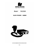
Repair manual
SECTION III
INSTALLATION
3-1. UNPACKING.
After unpacking the Model PA300, examine it for
damage that may have occurred in transit. If the
equipment has been damaged, file a claim immediately
with the carrier stating the extent of the damage.
Carefully check all envelopes, shipping labels and tags
before removing or destroying them.
3-2. MOUNTING BRACKET.
The PA300 comes equipped with a swinging
bracket which enables it to be mounted in a variety of
positions. Positioning the bracket above the unit allows
mounting to the underside of the dash. Positioning the
bracket below the unit will permit mounting on any
horizontal surface or, by the use of Federal’s TU-70
Tunnel Mount on the vehicle’s transmission hump.
The unit should be mounted in a position that is
both comfortable and convenient to the operator. Keep
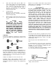
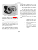
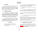
visibility and accessibility of controls in mind. To install
the unit under the dash, determine the mounting location
and proceed as follows (see figure 3-1).
CAUTION.
The unit must be installed in an
adequately ventilated area. Never install
near heater ducts.
A. Use one of the mounting brackets as a
template and scribe two drill positioning marks at the
selected mounting location under the dash.
B. Drill two 1-inch diameter holes at the
position marks.
C. Secure the mounting bracket to, the dash
with (2 each) ¼-20 x 3/4 hex head screws, ¼ split
lockwashers and ¼-20 hex nuts as shown in figure 3-1.
D. Secure the PA300 unit to the mounting
bracket with 1-20 x 3/8 hex head screws and I split
lockwashers.
E. Tilt the unit to the desired position. Tighten
the 1-20 x 3/8 hex head screws.
NOTE: When installing the PA300 on the transmission
hump, a Federal Model TU-70 Tunnel Mount is
recommended. The TU-70 Tunnel Mount is drilled and
tapped for the PA300 mounting bracket.
Follow the installation instructions packed with each unit.
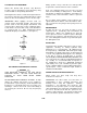
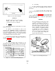
3-3. POWER CABLE INSTALLATION.
The power cable included in the carton is
equipped with a twelve-prong plug (P5) that mates with
the connector (J5) on the rear of the electronic siren (see
figure 3-2). The various wires on the connector must be
connected as described below.
4189
-3-