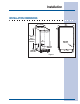
Installation INSTALLATION DIMENSIONS 24” (61) 14 - 15/16” (37.9) 34 - 1/8” (86.7) FULL RETRACT HEIGHT 5” (12.7) WATER VALVE WATER DRAIN WATER OUTLET 21 - 3/4” (55.
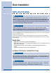
Drain Installation INSTALLING THE DRAIN ! CA UTION CAUTION PLEASE READ all instructions completely before attempting to install or operate the unit. All ice makers require a connection to the water supply and improper hook-up can result in substantial property damage! All water and drain connections MUST BE made by a licensed/qualified plumbing contractor. Failure to follow recommendations and instructions may result in damage and/or harm.
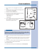
Drain Installation 1 Make certain the unit is not plugged into an electrical outlet. 2 Carefully push the power cord grommet through the hole in the back panel. See Figure 2. 3 Remove 12 screws and back panel. 4 Check that the clamps and hose connections are tight at the following areas illustrated in Figure 3: 9 • Discharge tube (A) • Drain tube (B) • Vent tube (C) 5 Place a suitable container beneath the pump’s discharge tube. (Container must be able to hold a minimum of one gallon of water.
10 Drain Pump Connection CONNECTING A DRAIN PUMP If a gravity drain connection is not available, and you have not purchased the E15IM60E with factory installed pump, we strongly recommend the use of the Electrolux EIMP60 drain pump. The Electrolux EIMP60 drain pump is available through your Dealer, or direct from Electrolux with complete installation instructions.
Site Preparation PREPARING THE SITE IMPOR TANT IMPORT It is extremely important that the unit is level. If it is not level, the ice mold will not fill evenly. This can cause a reduction in ice rate, uneven sized cubes or water spilling into the storage area which will cause the ice in the bin to melt pre-maturely. Remember that floors near drains have a tendency to slope towards the drain. 1 Position the unit on a flat, level surface, capable of supporting the entire weight of the unit.
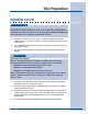
12 Site Preparation NO TE NOTE The door of the unit may be mounted on either side of the cabinet (see REVERSING THE DOOR). All units require zero clearance when installed flush with a cabinet or wall (see Figure 4). Electrolux stainless steel models require a minimum 2-3/4 inch handle clearance when installed against a wall or cabinet that extends beyond the front edge of the unit (see Figure 5).
Water Supply Connection CONNECTING THE WATER SUPPLY When connecting the water supply, follow these guidelines: • Review the local plumbing codes before you install the unit. • The water pressure should be between 20 and 120 psi. CA UTION CAUTION ! If you are using a filter system you will need to have at least 20 psi for 3 minutes every 15 minutes. • Make certain a SHUT-OFF VALVE is installed in the 1/4 inch water supply line.
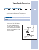
Water Supply Connection Figure 8 1 Locate the compression fitting and ferrule packed in the unit. Slide the compression fitting and ferrule over the 1/4 inch water supply line. Do not use thread sealing compound or tape. Using two wrenches, tighten the compression fitting on the supply line (see Figure 8). 2 Carefully bend the water supply line into position and connect the line to the solenoid valve (see Figure 9). Avoid kinking the water supply line.
Leveling LEVELING THE UNIT IMPOR TANT IMPORT It is extremely important that the unit is level. If it is not level, the ice mold will not fill evenly. This can cause a reduction in ice rate, uneven sized cubes or water spilling into the storage area which will cause the ice in the bin to melt pre-maturely. Remember that floors near drains have a tendency to slope towards the drain. 1 Use a level to check the levelness of the ice maker from front to back and from side to side (see Figure 11).
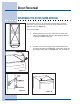
Door Reversal REVERSING THE DOOR (SOME MODELS) All Electrolux units may be left or right hand opening. The door opening is easily reversed by moving the hinge hard-ware to the opposite side (see Figure 13). To reverse the door: Figure 13 1 Remove top hinge screw pin (7/64" Allen wrench) from cabinet (see Figure 14). Remove door by tilting forward and lifting off bottom hinge pin.
Door Reversal HINGE SCREW PIN 3 Remove top hinge (3 screws), reinstall hinge screw pin, and remount on opposite side BOTTOM (see Figure 17). 4 Remove the two door closer inserts from the existing bottom hinge and install as shown on the new bottom hinge (see Figure 18). 5 Remove existing bottom hinge (3 screws) and remount on opposite side TOP. Remove hinge screw pin. 6 With bottom of door facing up, remove pivot plate (2 screws), flip over, and remount on opposite side of door (see Figure 19).