30" & 36" DUAL FUEL RANGE INSTALLATION INSTRUCTIONS (Model with Electric Oven and Gas Cooktop) INSTALLATION AND SERVICE MUST BE PERFORMED BY A QUALIFIED INSTALLER. IMPORTANT: SAVE FOR LOCAL ELECTRICAL INSPECTOR'S USE. READ AND SAVE THESE INSTRUCTIONS FOR FUTURE REFERENCE. OBSERVE ALL GOVERNING CODES AND ORDINANCES. If the information in this manual is not followed exactly, a fire or explosion may result causing property damage, personal injury or death.
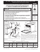
30" & 36" DUAL FUEL RANGE INSTALLATION INSTRUCTIONS (Model with Electric Oven and Gas Cooktop) 35 7/8" Min. (91.1 cm Min.) C B WALL WALL See note If there is a wall: 9" Min. (22.9 cm Min) Left side 18" Min. (45.7 cm Min.) G 13" Max. (33 cm Max.) A D If there is a wall: 9" Min. (22.9 cm Min.) Right side F E Grounded Wall Outlet or junction box location 24" Min. (61 cm Min.) 24 1/2" Max. (62.2 cm Max.) Do not pinch the power supply cord between the range and the wall.
0" & 36" DUAL FUEL RANGE INSTALLATION INSTRUCTIONS (Model with Electric Oven and Gas Cooktop) • Be sure your range is installed and grounded properly by a qualified installer or service technician. • This range must be electrically grounded in accordance with local codes or, in their absence, with the National Electrical Code ANSI/NFPA No. 70—latest edition in the United States or with CSA standard C22.1, Canadian Electrical Code, Part 1 in Canada.
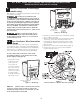
30" & 36" DUAL FUEL RANGE INSTALLATION INSTRUCTIONS (Model with Electric Oven and Gas Cooktop) 2. Factory Connected Power Supply Cord (Canada only) Center Line of Range 10" (25.4 cm) Your range is equipped with a factory-connected power cord (see Figure 3). Cord must be connected to a grounded 120/240 volt or 120/208 volt range outlet. If not outlet is available, have one installed by a qualified electrician. WALL R 7" Max. (17.8 cm Max.
30" & 36" DUAL FUEL RANGE INSTALLATION INSTRUCTIONS (Model with Electric Oven and Gas Cooktop) 5. Electrical Connection to the Range (US models only) This appliance is manufactured with the neutral terminal connected to the range. You may not ground the oven through the neutral (white) wire if oven is used in a new branch circuit installation (1996 NEC), mobile home, recreational vehicle, or where local codes do not permit grounding through the neutral (white) wire.
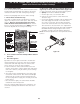
30" & 36" DUAL FUEL RANGE INSTALLATION INSTRUCTIONS (Model with Electric Oven and Gas Cooktop) 5.B Four Conductor Wire Connection 6. Direct Electrical Connection to to the Range the Circuit Breaker, Fuse Box or Junction Box 1. Remove the screws at the lower end of the rear wire access cover or panel, then remove the access cover or lift the lower part of the access panel to expose range terminal connection block (Fig. 7 or 8). 2.
30" & 36" DUAL FUEL RANGE INSTALLATION INSTRUCTIONS (Model with Electric Oven and Gas Cooktop) 6.B Four Conductor Wire Connection 7. Range Placement If oven is used in a new branch circuit installation (1996 NEC), mobile home, recreational vehicle, or where local codes do not permit connecting the appliance cable ground wire to the power supply cable neutral (white) wire you must use a 4 wire power supply cable (see figure 12): 1. Disconnect the power supply. 2.
30" & 36" DUAL FUEL RANGE INSTALLATION INSTRUCTIONS (Model with Electric Oven and Gas Cooktop) 8. Gas Supply Installation Assemble the flexible connector from the gas supply pipe to the pressure regulator in the following order: 1. Manual shutoff valve (not supplied) 2. 1/2" nipple (not supplied) 3. 1/2" flare union adapter (not supplied) 4. Flexible connector (not supplied) 5. 1/2" flare union adapter (not supplied) 6. 1/2" nipple (not supplied) 7.
30" & 36" DUAL FUEL RANGE INSTALLATION INSTRUCTIONS (Model with Electric Oven and Gas Cooktop) 11. Range Installation Do not use a flame to check for leaks from gas connections. Checking for leaks with a flame may result in a fire or explosion. 1. The back of the range may be installed directly against the wall. 2.
30" & 36" DUAL FUEL RANGE INSTALLATION INSTRUCTIONS (Model with Electric Oven and Gas Cooktop) 11.2 Check Operation 4. Adjust the "LOW" Setting of Regular Burner (see figure 17) on the Surface Burner Valves (Figure 18): a. Push in and turn control to LITE until burner ignites. b. Quickly turn knob to LOWEST POSITION. c. If burner goes out, reset control to OFF. d. Remove the surface burner control knob and decorative ring. e.
30" & 36" DUAL FUEL RANGE INSTALLATION INSTRUCTIONS (Model with Electric Oven and Gas Cooktop) 6. Operation of Oven Elements The oven is equipped with an electronic oven control. Each of the functions has been factory checked before shipping. However, it is suggested that you verify the operation of the electronic oven controls once more. Refer to the Use and Care Guide for operation. Follow the instructions for the Clock, Timer, Bake, Broil, Convection (some models) and Clean (some models) functions. 5.
30" & 36" DUAL FUEL RANGE INSTALLATION INSTRUCTIONS (Model with Electric Oven and Gas Cooktop) Important Safety Warning installed. (Use the diagram in figure 20 to locate bracket if template is not available.) 4. Mark on the floor the location of the mounting holes shown on the template (right and left position). For easier installation, 3/16" (4.8 mm) diameter pilot holes 1/2" (1.3 cm) deep can be drilled into the floor. 5. Remove template and place bracket on floor (see figure 20).
INSTRUCCIONES DE INSTALACIÓN PARA LA ESTUFA DE alimentación mixta (Para Modelos con un Horno Eléctrico y una Estufa a Gas) LA INSTALACIÓN Y EL SERVICIO DEBEN SER EFECTUADOS POR UN INSTALADOR CALIFICADO. IMPORTANTE: GUARDE ESTAS INSTRUCCIONES PARA USO DEL INSPECTOR LOCAL DE ELECTRICIDAD. LEA Y GUARDE ESTAS INSTRUCCIONES PARA REFERENCIA FUTURA. OBSERVE CÓDIGOS GOBERNANTES Y ORDENANZAS.
INSTRUCCIONES DE INSTALACIÓN PARA LA ESTUFA DE alimentación mixta (Para Modelos con un Horno Eléctrico y una Estufa a Gas) 35 7/8" Mín. (91.1 cm Mín.) C B PARED PARED Véa Nota Si hay una pared: 9" Mín. (22.9 cm Mín.) lado izquierdo 18" Mín. (45.7 cm Mín.) G 13" Max. (33 cm Max.) A D Si hay una pared: 9" Mín. (22.9 cm Mín.) lado derecho F E Tomacorriente de pared puesto a tierra 24" Mín. (61 cm Mín.) 24 1/2" Máx. (62.2 cm Máx.) No pellizque el cordón eléctrico entre la estufa y la pared.
INSTRUCCIONES DE INSTALACIÓN PARA LA ESTUFA DE alimentación mixta (Para Modelos con un Horno Eléctrico y una Estufa a Gas) • Asegúrese de que la estufa sea instalada y conectada a tierra en forma apropiada por un instalador calificado o por un técnico. • Esta estufa debe ser eléctricamente puesta a tierra de acuerdo con los códigos locales, o en su ausencia, con el Código Eléctrico Nacional ANSI/ NFPA No. 70, última edición.
INSTRUCCIONES DE INSTALACIÓN PARA LA ESTUFA DE alimentación mixta (Para Modelos con un Horno Eléctrico y una Estufa a Gas) 2. Cordón de fuente de energía conectado de fabrica (Canadá solamente) Estufa de 30" y 36": Utilice un cordón de fuente de energía de 30 amperios.
INSTRUCCIONES DE INSTALACIÓN PARA LA ESTUFA DE alimentación mixta (Para Modelos con un Horno Eléctrico y una Estufa a Gas) Riesgo de Choque Eléctrico • Se requiere una conexión a tierra en este electrodoméstico. • No lo conecte a la corriente eléctrica hasta que el aparato haya sido puesto a tierra permanentemente. • Desconecte la corriente eléctrica a la caja de empalmes antes de hacer la conexión eléctrica.
INSTRUCCIONES DE INSTALACIÓN PARA LA ESTUFA DE alimentación mixta (Para Modelos con un Horno Eléctrico y una Estufa a Gas) Terminal de color plata Bloque terminal d Co de e la rd ó m pl n on ac ta a je Alambre negro Un retenedor provisto por le usuario se debe instalar en esta localización 1-1/8” Dia. Agujero de la conexión Alambre directa. Retira negro la arandela pre-cortada para 1-3/8” dia.
INSTRUCCIONES DE INSTALACIÓN PARA LA ESTUFA DE alimentación mixta (Para Modelos con un Horno Eléctrico y una Estufa a Gas) Cable de la fuente de alimentación Alambre Alambres blanco (Neutro) negros Alambres rojos Alambre neutro Alambres rojos Caja empalmes Alambres desnudos o verdes Alambre blanco (Neutro) Alambres desnudos o verdes Cable de la estufa Cable de la fuente de alimentación Alambre blanco Alambres negros Alambre blanco Conductor de unión listado-U.L.
INSTRUCCIONES DE INSTALACIÓN PARA LA ESTUFA DE alimentación mixta (Para Modelos con un Horno Eléctrico y una Estufa a Gas) 7. Estufa - Colocación 8. Instalación de la alimentación de gas Para eliminar el riesgo de quemaduras o fuego por el contacto de superficies sobrecalentadas, cualquier espacio de almacenaje en los gabinetes situados sobre la estufa debe ser evitado.
INSTRUCCIONES DE INSTALACIÓN PARA LA ESTUFA DE alimentación mixta (Para Modelos con un Horno Eléctrico y una Estufa a Gas) Monte el conector flexible desde el tubo de suministro de gas hasta el regulador de presión según este orden: 1. Válvula de cierre manual (no incluido) 2. Boquilla de 1/2" (no incluido) 3. 1/2" Adaptador de unión (no incluido) 4. Conector flexible (no incluido) 5. 1/2" Adaptador de unión (no incluido) 6. Boquilla de 1/2" (no incluido) 7.
INSTRUCCIONES DE INSTALACIÓN PARA LA ESTUFA DE alimentación mixta (Para Modelos con un Horno Eléctrico y una Estufa a Gas) 11. Instalación de la estufa 11.2 Comprobación del Funcionamiento Consulte el Manual del Usuario incluido con la estufa para instrucciones de operación y instrucciones para el cuidado y limpieza de su estufa. 1. La parte trasera de la estufa puede ser directamente instalada a ras con la pared trasera de la estructura. 2.
INSTRUCCIONES DE INSTALACIÓN PARA LA ESTUFA DE alimentación mixta (Para Modelos con un Horno Eléctrico y una Estufa a Gas) 4. Ajuste bajo ("LO") para la válvula de los quemadores de superficie estándar (Figuras 17 y 18) a. Presione y gire el control hasta la posición LITE para prender los quemadores. b. Gire rápidamente gire la perilla a la POSICIÓN MAS BAJA. c. Si el quemador se apaga, reajuste el control a OFF. d. Retire la perilla y el anillo del quemador de superficie. e.
INSTRUCCIONES DE INSTALACIÓN PARA LA ESTUFA DE alimentación mixta (Para Modelos con un Horno Eléctrico y una Estufa a Gas) Importante Advertencia de Seguridad Para reducir el riesgo de que la estufa se vuelque, es necesario asegurarla al piso instalando los soportes antivuelco y los tornillos suministrados con la estufa. Las piezas se encuentran en un saco de plástico en el horno.
Instructions d'INSTALLATION pour les cuisinières 30" et 36" À alimentation mixte (Modèles avec four électrique et table de cuisson à gaz) UN INSTALLATEUR QUALIFIÉ DOIT EFFECTUER L’INSTALLATION ET LE SERVICE IMPORTANT: CONSERVEZ CES INSTRUCTIONS POUR LES INSPECTEURS LOCAUX LISEZ CES INSTRUCTIONS ET CONSERVEZ‑LES POUR RÉFÉRENCES ULTÉRIEURES Si les instructions de ce manuel ne sont pas suivies à la lettre, il pourrait en résulter un incendie ou une explosion susceptible de causer des dommages matériels, des bl
Instructions d'INSTALLATION pour les cuisinières 30" et 36" À alimentation mixte (Modèles avec four électrique et table de cuisson à gaz) 35 7/8" Min. (91.1 cm Min.) C B MUR MUR Voir la note S'il y a un mur: 9" Min. (22.9 cm Min.) du côté gauche 18" Min. (45.7 cm Min.) G 13" Max. (33 cm Max.) A D S'il y a un mur: 9" Min. (22.9 cm Min.) du côté droit F E 24" Min. (61 cm Min.) 24 1/2" Max. (62.2 cm Max.
Instructions d'INSTALLATION pour les cuisinières 30" et 36" À alimentation mixte (Modèles avec four électrique et table de cuisson à gaz) • Assurez‑vous que votre cuisinière est correctement installée et mise à la terre par un installateur ou un technicien d’entretien qualifié. • Le circuit électrique de cette cuisinière doit être mis à la terre conformément aux règlements locaux, ou en leur absence, à la norme canadienne d’électricité, ACNOR C22.1, partie 1.
Instructions d'INSTALLATION pour les cuisinières 30" et 36" À alimentation mixte (Modèles avec four électrique et table de cuisson à gaz) endroit où les codes locaux interdisent la mise à la terre au moyen du conducteur neutre, un cordon d'alimentation de 4 conducteurs d'un minimum de 125/250 volts, certifié pour l'utilisation avec cuisinière doit être utilisé (voir Figure 10). 2.
Instructions d'INSTALLATION pour les cuisinières 30" et 36" À alimentation mixte (Modèles avec four électrique et table de cuisson à gaz) 5. Connexions électriques à la cuisinière (États-Unis seulement ) Cet appareil est muni d'une borne neutre branchée au châssis.
Instructions d'INSTALLATION pour les cuisinières 30" et 36" À alimentation mixte (Modèles avec four électrique et table de cuisson à gaz) 5.B Pour une connexion à un câble 6. Connexions électriques au d'alimentation à 4 conducteurs système électrique de la résidence 1.
Instructions d'INSTALLATION pour les cuisinières 30" et 36" À alimentation mixte (Modèles avec four électrique et table de cuisson à gaz) 7. Emplacement de la cuisinière 6.B Pour une connexion à une boîte Pour éliminer les risques de brûlures ou de feu, en étendant le bras au‑dessus des surfaces de cuisson chaudes, évitez d’installer des armoires au‑dessus de la cuisinière.
Instructions d'INSTALLATION pour les cuisinières 30" et 36" À alimentation mixte (Modèles avec four électrique et table de cuisson à gaz) 8. Alimentation en gaz - Installation Assemblez le connecteur flexible du conduit d’alimentation en gaz au régulateur de pression dans l’ordre qui suit: 1. Robinet d’arrêt manuel (non fourni) 2. Mamelon ½" (non fourni) 3. Adaptateur de raccord évasé ½" (non fourni) 4. Connecteur flexible (non fourni) 5. Adaptateur de raccord évasé ½" (non fourni) 6.
Instructions d'INSTALLATION pour les cuisinières 30" et 36" À alimentation mixte (Modèles avec four électrique et table de cuisson à gaz) 11. Installation de la cuisinière N’utilisez pas de flamme nue pour vérifier les fuites de gaz. La détection des fuites à l’aide d’une flamme pourrait provoquer un incendie ou une explosion. 1. L'arrière de la cuisinière doit être appuyé directement contre le mur. 2.
Instructions d'INSTALLATION pour les cuisinières 30" et 36" À alimentation mixte (Modèles avec four électrique et table de cuisson à gaz) 11.2 Vérification du fonctionnement 4. Réglez la position LOW des robinets (voir Figure 17) des brûleurs de surface réguliers (voir Figure 18): A. Appuyez et tournez le bouton de commande à LITE jusqu’à ce que le brûleur s’allume. b. Tournez rapidement le bouton à la position la plus basse (LOW). c. Si le brûleur s’éteint, remettez le bouton à la position arrêt (OFF). d.
Instructions d'INSTALLATION pour les cuisinières 30" et 36" À alimentation mixte (Modèles avec four électrique et table de cuisson à gaz) Convection– Lorsque le four est réglé à CONV. BAKE/ ROAST, le ventilateur de convection se met à tourner. Le ventilateur de convection arrête de tourner lorsque la porte du four est ouverte durant la cuisson par convection. 6. Fonctionnement des éléments du four Ce four est équipé d’un contrôleur électronique.
Instructions d'INSTALLATION pour les cuisinières 30" et 36" À alimentation mixte (Modèles avec four électrique et table de cuisson à gaz) 5. Enlevez le gabarit et placez les supports sur le plancher (voir figure 20). Alignez les trous dans les supports avec les trous tracés sur le plancher et fixez les supports à l'aide des vis fournies. Les supports doivent être fixés sur un plancher solide. Si vous les fixez à un plancher en béton, percez d’abord des trous pilotes de 3/16" (0.