Use E_ Care Guide lnstaWWation Instructions Ve n _ 1_o o d
J READ AND SAVE THESE INSTRUCTIONS [] [] [] [] [] [] [] Read all instructions [] [] [] before installing [] [] [] [] [] [] [] [] [] [] [] [] [] For toll-free telephone 1=877= 4ELECTROLUX [] [] [] Electrolux Post Office Al! rights Home Box 212378, reserve& Products, Augusta, Printed [] [] [] [] support in the U.S. and Canada: (1 =877=435=3287) For online support and Intemet product www.electro_uxusa.
J TABIIII,,,,,,,,,,E OF CONTENTS [] [] [] [] [] [] [] [] [] [] [] FindingInformation .............................................. 2 PleaseReadAnd SaveThis Guide...................2 MakeA RecordForQuick Reference................2 Questions........................................................... 2 TableOfContents.............................................. 3 Safety..................................................................... 4 ImportantSafetyInstructions.............................
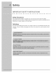
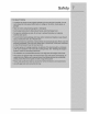
Safety Precautions Do not attempt to install or operate your unit untie you have read the safety precautions in this manual. Safety items throughout Warning or Caution based on the risk type, this manual are labeled with a Definitions Z_ This is the safety alert symbol. hazards.
SAFETY PRECAUTIONS [] [] [] [] [] [] [] [] [] [] [] [] [] [] [] [] [] [] [] [] m []
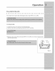
ORERATIHG YOUR HOOD [] [] [] [] [] [] The hood is operated [] [] [] [] [] [] using the slide controls The light switch turns the halogen [] [] [] [] [] [] [] [] [] under the front edge of the hood. lights on and off. The blower on/off switch turns the blower on to the running speed set by the blower speed control. The blower must be BLOWER ON/OFF SWHTCR turned on and off using this switch. The blower speed control changes blower (1-2-3).
HALOGEN BULBS [] [] [] This range To change 1 Loosen 2 Remove [] hood [] [] requires [] [] [] [] [] four (4) halogen [] bulbs [] [] (Type [] [] MR16, [] [] [] [] [] 12V, 20W). bulbs: the ring nut by turning it counterclockwise. the bulb by pulling downward (DO NOT ROTATE). 3 Replace with a bulb of the same type (MR16, bulb with bare hands. 12V, 20W).
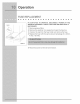
FUSE REPIIII,,,,,,,,,AC EMENT [] [] [] [] [] [] [] [] [] [] [] [] mFUGHTS FAiL TO OPERATE, SERVICE ENTRANCE. CHECK NECESSARY. [] [] [] [] [] [] [] [] DmSCONNECT POWER AT THE THE FUSE AND REPLACE mF 1 Remove grease 2 Remove the electrical 3 Unscrew filters. the cap from the fuse holder and remove the fuse. box support and open the fuse box. 4 Replace the fuse with the same size and amperage 4 amp, 125 volt). Figure 3 5 Reconnect [] power at the service entrance.
Care an Cleanin ClIII ,EANINGTHE FIL,,,,RS AND HOOD [] [] [] [] [] [] Proper maintenance Grease Filters [] [] [] of the Range [] [] Hood FILTERS" [] [] [] [] [] [] [] Hood will assure proper performance The grease fi_ters should be cleaned Grease filters are dishwasher safe, See "INSTALL [] frequently. section for removal Use a warm detergent and installation [] [] [] of the unit, solution, instructions.
! INSTAl,I,ATIONPLANNING [] [] [] [] [] [] [] [] [] A qualified installer must complete installation is your responsibility. [] [] [] [] the installation [] [] [] [] [] [] of this built-in appliance. [] [] Proper Carefully check the location where the hood is to be installed. The hood should be placed for convenient access. Make certain that electrical power can be provided in the selected location.
VERIFY PACKAGE CONTENTS [] [] [] Unpack [] [] [] [] [] [] [] [] [] [] [] [] [] [] [] [] [] [] [] hood and check contents. You should receive: 1 - Hood 1 - Decorative Flue Assembly 1 - Support Frame 1 - Duct Collar 1 - Parts Bag containing: 8 - Washers ® 6.4 4 - Washers e 4.5 4 - Lag Bolts 8 - Mounting Screws 4 - Hex Nuts 1 - Installation Instructions 2 - Warranty (3.9 X 9.5mm Pan Head) Cards 4 REX NUTS DUCT DECORATIVE FLUE SUPPORT FRAME 8 WASHERS _6.
! INSTALLING THE DUCTWORK [] [] [] [] [] 1 Decide where 2 A straight, [] [] [] the ductwork [] [] [] [] will run between [] [] [] [] [] [] [] the hood and the outside. short duct run will allow the hood to perform [] [] [] Figure 5. most efficiently. 3 Long duct runs, elbows, and transitions will reduce the performance of the hood. Use as few of them as possible. Larger ducting may be required for best performance with longer duct runs. 4 ROOF Install a roof or wall cap.
J Jation INSTAI,,,,,,,,,,I,,,,,,,,,,ING THE SUPPORT SYSTEB [] [] [] [] [] 1 At hood location, using dimensions [] [] [] [] [] [] [] [] install 2 x 4 cross framing shown in Figure 6. [] [] between distance [] [] [] [] [] [] ceiling joists 2 Finish the ceiling surface. Be sure to mark the location ceiling joists and cross framing. 3 Measure the ceiling height and determine top and bottom of hood.
! CONNECTINGTHE DECORATIVEFLUE [] [] [] [] [] [] [] [] [] [] [] [] 1 Secure the upper flue to the upper support x 9.5mm). 2 Insert the bower flue moving it completely with retaining screws (3.9 x 9.5mm). MOUNTING SCREWS (s.9 xg.5mm) iNSERT THE LOWER [] [] [] [] [] [] [] frame with the mounting towards [] [] screws [] (3.
MOUNTINGTHE HOOD TO SUPPORT FRAME [] [] [] [] [] [] [] [] 1 Insert four (4) bolts through [] [] [] [] [] [] [] [] [] [] [] [] r the top of the hood from the inside, 2 Use four (4) nuts and four (4) washers [] to secure hood to support frame. INSTAL,LINGTHE EIIII,,,,,,,,,,ECTRICAIIII .......... [] [] [] 1 Remove box. [] [] [] [] [] the wiring box cover.
[ CONNECTINGTHE DUCTWORK [] [] [] [] [] [] [] [] [] [] [] [] [] 1 Use 8" round metal duct to connect the ductwork above, LOWER FLUE [] [] [] the discharge [] [] [] [] [] [] collar on the hood to 2 Use duct tape to make all joints secure and air tight, RETAINING SCREWS 3 Remove the two temporary it in place on the hood, retaining screws from the lower flue and set 4 Secure decorative flue to hood with two mounting pan head mounting screws.
INSTALLINGTHE FIL,,,,,, R(S) [] [] [] [] [] [] [] [] [] [] [] [] [] [] [] [] [] [] [] [] [] 1 To remove the grease filter, grip the latch and pull it down. This will disengage filters from the hood. Tilt the filter downward and remove. [] the 2 To install the grease filter, align rear filter tabs with slots in the hood. Pull latch tab down, push filter up into position and release the tab. Make sure the filter is securely engaged after installation.
m First, review the recommended checks listed in the Troubleshooting Guide. Then, be certain that the appliance has been installed properly and is being operated correctly. Familiarize yourself with the warranty terms and conditions listed in the Warranty section. If the above checks have been completed and the problem has not yet been remedied, contact the dealer where you purchased the unit. State the Model and Serial number and explain the problem.
TROUBIIII,,,,,,,,,, HOOTING GUIDE [] [] m m [] Troub/eshoedng [] [] [] [] [] m m . What to check m [] [] [] [] when preblems [] m m [] [] occur Problem Possible Cause Remedy Nothing works. Vent power supply interruptedor not energized. Have electrician check power supply, includinghouse circuit breaker and fuses. Lights do not turn on. A loose or burned out light. Check the light. Blown fuse. Check lamp fuse and replace if open.
1 Do not operate the blower at a speed that is higher than necessary to remove the cooking exhaust. Running at excessive speeds removes more air from the inside of the house that must be replaced by outside air. This may be especially costly when the housing air conditioning or heating system is in operation. 2 Clean filters and greasedaden 3 Turn off the blower as soon as all cooking eliminated.
Y HOODWARRANTYYour hood isprotected by this warranty WARRANTY PERIOD THROUGH OURAUTHORIZED SERVICERS, WEWILL: FULLONE-YEAR WARRANTY Oneyearfrom originalpurchase date. Payallcostsforrepairing or replacinganypartsofthis product whichproveto bedefective inmaterialsor workmanship.