GB Instruction Manual 3 ES Manual de instrucciones 12 DE Bedienungsanleitung 21 PT Manual de Instruções 30 TU Kullanma Kilavuzu 39 EFC 6540 EFC 7540 EFC 9540 EFC 1540
Dear Customer, If you follow the recommendations contained in this Instruction Manual, your appliance will give you constant high performance and will remain efficient for many years to come.
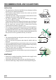
RECOMMENDATIONS AND SUGGESTIONS INSTALLATION • The manufacturer will not be held liable for any damages resulting from incorrect or improper installation. • The minimum safety distance between the cooker top and the extractor hood is 650 mm. • Check that the mains voltage corresponds to that indicated on the rating plate fixed to the inside of the hood. • For Class I appliances, check that the domestic power supply guarantees adequate earthing.
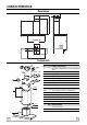
CHARACTERISTICS 650 min. 60 740 870 1200 64 42 Dimensions 598-698-898-1198 598-898 300 490 260 108 150 Components 15 14.1 7.3 12a 7.2.1 9 2.1 12c 2 2.2 11 12a 11 Ref. 1 2 2.1 2.2 9 14.1 15 Q.ty Product Components 1 Hood Body, complete with: Controls, Light, Blower, Filters 1 Telescopic Chimney comprising: 1 Upper Section 1 Lower Section 1 Reducer Flange ø 150-120 mm 2 Air Outlet Connection Extension 1 Air Outlet Connection Ref. Q.ty Installation Components 7.2.
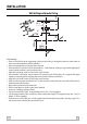
INSTALLATION 1÷2 Wall drilling and bracket fixing 650 min. 12a 116 116 320 11 X 7.2.1 Wall marking: • Draw a vertical line on the supporting wall up to the ceiling, or as high as practical, at the centre of the area in which the hood will be installed. • Draw a horizontal line at 650 mm above the hob. • Place bracket 7.2.1 on the wall as shown about 1-2 mm from the ceiling or upper limit aligning the centre (notch) with the vertical reference line.
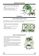
Mounting the hood body • Before attaching the hood body, tighten the two screws Vr located on the hood body mounting points. • Hook the hood body onto the screws 12a • Fully tighten support screws 12a • Adjust screws Vr to level the hood body. Vr 12a Connections DUCTED VERSION AIR EXHAUST SYSTEM When installing the ducted version, connect the hood to the chimney using either a flexible or rigid pipe ø 150 or 120 mm, the choice of which is left to the installer.
ELECTRICAL CONNECTION • Connect the hood to the mains through a two-pole switch having a contact gap of at least 3 mm. • Remove the grease filters and verify that the connector of the feeding cable is correctly inserted in the socket placed on the side of the fan Enlever les filtres à graisse et s'assurer que le connecteur Flue assembly Upper exhaust flue • Slightly widen the two sides of the upper flue and hook them behind the brackets 7.2.1, making sure that they are well seated.
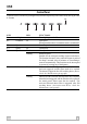
USE Control Panel The hood can be switched on pushing directly onto the requested speed without firstly having to select 0/1 button. S1 L KEY L T1 0/1 Light 0/1 Motor LED T2 T3 T4 Speed Speed Speed on on Fixed Flashing S1 Led Fixed on Flashing GB T1 T2 T3 T4 FUNCTIONS Turns lighting on and off. First speed. When pressed for about 1 seconds the motor is switched off. Second speed. Third speed. Max. speed Intensive speed. Suitable for the strongest cooking vapours and odours.
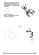
MAINTENANCE Grease filters CLEANING METAL SELF- SUPPORTING GREASE FILTERS Alarm signal reset • Switch off the lights and extractor motor. • Press button T3 for at least 3 seconds, until the leds start to flash. Cleaning the filters • The filters must be cleaned every 2 months of operation, or more frequently for particularly heavy usage, and can be washed in a dishwasher. • Remove the filters one at a time by pushing them towards the back of the group and pulling down at the same time.
• The filter is not washable and cannot be regenerated. It must be replaced when led S1 flashes or at least every 4 months. The alarm signal will only light up when the extractor motor is switched on. Alarm signal reset • Switch off the lights and extractor motor. • Press button T3 for at least 3 seconds, until the leds start to flash.
This appliance conforms to European Low Voltage Directive 73/23/CEE governing electrical safety, European Directive 89/ 336/CEE on Electromagnetic Compatibility and Directive 93/68/CEE regarding CE Marking. Este aparato es conforme con la normativa europea sobre baja tensión C.E.E. 73/23 correspondiente a la seguridad eléctrica y a las normativas europeas : C.E.E. 89/336 sobre la compatibilidad electromagnética y C.E.E. 93/68 sobre la marca CE.