EFC 90905 Instructions Manual Manual de instrucciones Manual de Instruções
Instructions Manual INDEX RECOMMENDATIONS AND SUGGESTIONS ......................................................................................................................5 CHARACTERISTICS..............................................................................................................................................................6 INSTALLATION ..................................................................................................................................................
Manual de instrucciones ÍNDICE CONSEJOS Y SUGERENCIAS ...........................................................................................................................................12 CARACTERÍSTICAS ............................................................................................................................................................13 INSTALACIÓN..................................................................................................................................
Manual de Instruções ÍNDICE CONSELHOS E SUGESTÕES ............................................................................................................................................19 CARACTERÍSTICAS ............................................................................................................................................................20 INSTALAÇÃO .....................................................................................................................................
RECOMMENDATIONS AND SUGGESTIONS INSTALLATION • The manufacturer will not be held liable for any damages resulting from incorrect or improper installation. • The minimum safety distance between the cooker top and the extractor hood is 650 mm. • Check that the mains voltage corresponds to that indicated on the rating plate fixed to the inside of the hood. • For Class I appliances, check that the domestic power supply guarantees adequate earthing.
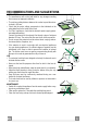
CHARACTERISTICS max. 765 490 205 100 598 - 698 - 898 210 150 650 min. 18 240 560 min. 560 Dimensions Components Ref. Q.ty Product Components 1 1 Hood Body, complete with: Controls, Light, Blower, Filters 2 1 Telescopic Chimney comprising: 2.1 1 Upper Section 2.2 1 Lower Section 9 1 Reducer Flange ø 150-120 mm 15 1 Air Outlet Connection 12a 7.2.1 15 9 11 12c 2.1 12c 2 Ref. Q.ty Installation Components 7.1 2 Hood Body Fixing Brackets 7.2.
INSTALLATION 1÷2 Wall drilling and bracket fixing 95 210 95 H 650 min. 7.1 X 7.2.1 Wall marking: • Draw a vertical line on the supporting wall up to the ceiling, or as high as practical, at the centre of the area in which the hood will be installed. • Draw a horizontal line at 650 mm above the hob for installation without the back panel, or at height H (H=height of the visible part of the panel) for installation with the back panel. • Place bracket 7.2.
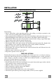
Mounting the hood body 12.d • Screw the two screws 12d supplied onto the brackets 7.1. • Hook the hood body onto the bracket 7.1, centring it around the vertical line. • Use the adjusting screws 12d underneath the hood to level the hood body. 7.1 Connections DUCTED VERSION AIR EXHAUST SYSTEM When installing the ducted version, connect the hood to the chimney using either a flexible or rigid pipe ø 150 or 120 mm, the choice of which is left to the installer.
ELECTRICAL CONNECTION • Connect the hood to the mains through a two-pole switch having a contact gap of at least 3 mm. • Remove the grease filters (see paragraph Maintenance) being sure that the connector of the feeding cable is correctly inserted in the socket placed on the side of the fan. Flue assembly Upper exhaust flue • Slightly widen the two sides of the upper flue and hook them behind the brackets 7.2.1, making sure that they are well seated.
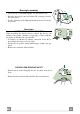
USE 3 1 2 0 1 0 1 V L M L Light Switches the lighting system on and off M Motor Switches the extractor motor on and off V Speed Sets the operating speed of the extractor: 1. Low speed, used for a continuous and silent air change in the presence of light cooking vapour. 2. Medium speed, suitable for most operating conditions given the optimum treated air flow/noise level ratio. 3. Maximum speed, used for eliminating the highest cooking vapour emission, including long periods.
MAINTENANCE Grease filters CLEANING METAL SELF- SUPPORTING GREASE FILTERS • The filters must be cleaned every 2 months of operation, or more frequently for particularly heavy usage, and can be washed in a dishwasher. • Remove the filters one at a time by pushing them towards the back of the group and pulling down at the same time. • Wash the filters, taking care not to bend them. Allow them to dry before refitting. • When refitting the filters, make sure that the handle is visible on the outside.
The symbol on the product or on its packaging indicates that this product may not be treated as household waste. Instead it shall be handed over to the applicable collection point for the recycling of electrical and electronic equipment. By ensuring this product is disposed of correctly, you will help prevent potential negative consequences for the environment and human health, which could otherwise be caused by inappropriate waste handling of this product.