EFC 9541 Instructions Manual Bedienungsanleitung
Instructions Manual INDEX RECOMMENDATIONS AND SUGGESTIONS...................................................................................................................... 4 CHARACTERISTICS.............................................................................................................................................................. 5 INSTALLATION .................................................................................................................................................
Bedienungsanleitung INHALTSVERZEICHNIS EMPFEHLUNGEN UND HINWEISE....................................................................................................................................13 CHARAKTERISTIKEN .........................................................................................................................................................14 MONTAGE.....................................................................................................................................
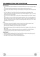
RECOMMENDATIONS AND SUGGESTIONS INSTALLATION • The manufacturer will not be held liable for any damages resulting from incorrect or improper installation. • The minimum safety distance between the cooker top and the extractor hood is 650 mm. • Check that the mains voltage corresponds to that indicated on the rating plate fixed to the inside of the hood. • For Class I appliances, check that the domestic power supply guarantees adequate earthing.
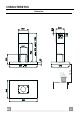
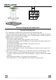
CHARACTERISTICS 650 min.
Components Ref. 1 2 2.1 2.2 7.1 7.1a 7.1b 9 10 15 24 25 Q.ty Product Components 1 Hood Body, complete with: Controls, Light, Blower, Filters 1 Telescopic Chimney comprising: 1 Upper Section 1 Lower Section 1 Telescopic frame complete with extractor, consisting of: 1 Upper frame 1 Lower frame 1 Reducer Flange ø 150-120 mm 1 Flange ø 150 1 Air Outlet Connection 1 Junction box 2 Pipe clamps Ref. 11 12c 12e 12f 12g 12h 21 22 23 Q.ty 4 6 2 4 4 4 1 4 4 21 23 11 22 12h 7.1a 15 12g 7.1 10 7.
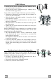
INSTALLATION Drilling the Ceiling/shelf and fixing the frame DRILLING THE CEILING/SHELF • Use a plumb line to mark the centre of the hob on the ceiling/support shelf. • Place the drilling template 21 provided on the ceiling/support shelf, making sure that the template is in the correct position by lining up the axes of the template with those of the hob. • Mark the centres of the holes in the template.
FIXING THE frame • Loosen the two screws fastening the lower chimney and remove this from the lower frame. • Loosen the two screws fastening the upper chimney and remove this from the upper frame. If you wish to adjust the height of the frame, proceed as follows: • Unfasten the eight metric screws joining the two columns, located at the sides of the frame. • Adjust the frame to the height required, then replace all the screws removed as above.
Recirculation version air outlet 15 • Fix the connection 15 to the frame using the 4 screws provided. • Fix the flange 10 to the lower opening of the connection 15. • Connect the hood air outlet to the flange in the lower part of the junction using a rigid or flexible ø 150 tube (by installer’s choice). 10 12c Flue assembly - Mounting the hood body • Position the upper chimney section and fix the upper part to the frame using the 2 screws 12c (2,9 x 6,5) provided.
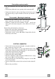
USE S1 L T1 T2 T3 T4 Control Panel The hood can be switched on pushing directly onto the requested speed without firstly having to select 0/1 button. KEY LED FUNCTIONS L 0/1 Light Turns lighting on and off. T1 0/1 Motor on First speed. When pressed for about 1 seconds the motor is switched off. T2 Speed on Second speed. T3 Speed on Third speed. T4 Speed Fixed Max. speed Flashing Intensive speed. Suitable for the strongest cooking vapours and odours.
MAINTENANCE REMOTE CONTROL (OPTIONAL) The appliance can be controlled using a remote control powered by a 1.5 V carbon-zinc alkaline batteries of the standard LR03-AAA type. • Do not place the remote control near to heat sources. • Used batteries must be disposed of in the proper manner. Grease filters CLEANING METAL SELF- SUPPORTING GREASE FILTERS Alarm signal reset • Switch off the lights and extractor motor. • Press button T3 for at least 3 seconds, until the leds start to flash.
Activated charcoal filter (Recirculation version) • The filter is not washable and cannot be regenerated. It must be replaced when led S1 flashes or at least every 4 months. The alarm signal will only light up when the extractor motor is switched on. Alarm signal activation • In Recirculation version Hoods, the Filter saturation alarm can be enabled on installation or at a later date. Turn the Lights and the suction Motor off.
Dir. 89/336/CEE 73/23/CEE 93/68/CEE The symbol on the product or on its packaging indicates that this product may not be treated as household waste. Instead it shall be handed over to the applicable collection point for the recycling of electrical and electronic equipment. By ensuring this product is disposed of correctly, you will help prevent potential negative consequences for the environment and human health, which could otherwise be caused by inappropriate waste handling of this product.