User manual Manual de instrucciones Manual de instruções EFC 6690 - EFC 9690
electrolux safety warnings Welcome to the world of Electr olux Electrolux Thank you for choosing a first class product from Electrolux, which hopefully will provide you with lots of pleasure in the future. The Electrolux ambition is to offer a wide variety of quality products that make your life more comfortable. You find some examples on the cover in this manual. Please take a few minutes to study this manual so that you can take advantage of the benefits of your new machine.
electr olux contents electrolux Contents GB Safety warnings ................................5 Description of the Appliance ..............7 Control Panel .................................... 8 Maintenance and Care .................... 12 Special accessories ........................ 17 Something Not Working .................. 17 Installation .......................................
electrolux safety warnings 5 GB Safety warnings For the user • The cooker hood is designed to extract unpleasant odours from the kitchen, it will not extract steam. • Always cover lighted elements, to prevent excess heat from damaging the appliance. In the case of oil, gas and coal fired cookers it is essential to avoid open flames. • Also, when frying, keep the deep frying pan on the cooker top/cooker under careful control. • The hot oil in the frying pan might ignite due to overheating.
GB electr olux safety warnings electrolux For the installer • When used as an extractor unit, the hood must be fitted with a hose having preferably the same diameter as the outlet hole. Attention: The hose is not supplied and must be purchased separately.
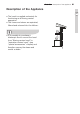
electrolux description of the appliance 7 Description of the Appliance GB • The hood is supplied exclusively for functioning as a filtering version apparatus. • The fumes and steam are aspirated, filtered and returned into the kitchen. • It is possible to purchase a telescopic flue to convert the hood from “filtering version hood” to “aspiration version hood”, (see “special accessories” chapter) and therefore convey the steam and smells outside.
electr olux control panel electrolux Control Panel GB • Best results are obtained by using a low speed for normal conditions and a high speed when odours are more concentrated. Turn the hood on a few minutes before you start cooking. The hood should be left on after cooking for about 15 minutes or until all the odours have disappeared. ect ventilation: If the cooker hood is to work correctly there must be an • Corr Correct under pressure in the kitchen.
electrolux control panel Control of suction speed (power) The selection of the suction speed (power) is cyclical, according to the speed sequences “”stand-by - 1-2-34- Stand by -1-2-”… so that at every AR touch of the UPPER P PAR ART of the control bar the suction speed (power) increases by a level and then switches off (stand-by) if the control bar is touched again when the hood is at suction speed (power) 4.
GB electr olux control panel electrolux It is possible to determine what suction speed (power) the hood is in when the bar is equipped with a led that changes colour on the basis of the suction speed (power), as follows: • Hood in stand-by: LED OFF • 1st suction speed (power) - led GREEN • 2st suction speed (power) - led ORANGE (amber) • 3st suction speed (power) - led RED • 4st suction speed (power) - led RED (FLASHING) Note: the 4th suction speed (power) remains on for 5 minutes, after which the suc
electrolux control panel Reset and configuration of the filters saturation signal Switch the hood on at any speed (see paragraph above “Selection of the suction speed (power)” Reset anti-fat filter saturation signal (GREEN LED FLASHING on the contr ol level) control First pr oceed with the maintenance of proceed the filter as described in the corr esponding paragraph.
electr olux maintenance and care electrolux Maintenance and Care GB • Before performing any maintenance operation, isolate the hood from the electrical supply by switching off at the connector and removing the connector fuse. Or if the appliance has been connected thr ough a plug and socket, then the through plug must be rremoved emoved fr om the socket.
electrolux maintenance and care To reactivate the charcoal, the filter should be dried in an oven for 10 minutes with a maximum temperature of 100º C. After approximately three years of use, the charcoal filter should be replaced with a new one, as the odour reduction capacity will be reduced. • Always specify the hood model code number and serial number when ordering replacement filters. This information is shown on the rating plate located on the inside of the unit.
GB electr olux maintenance and care electrolux Dismantling and mounting the filter in the upper part of the hood • With a small screwdriver lift the 3 tongues that block the filters and remove the filters. • Remove the frame that blocks the active carbon filter. • Carry out the montage following the procedure described above in the reverse sequence sequence..
electrolux maintenance and care 15 Changing the light bulb(s) GB • Disconnect the cooker hood from the mains supply supply.. • Prior to touching the light bulbs ensure they are cooled down. • Side lights: - Remove the protection glass with a screwdriver. - Replace the bulb with a new one with the same characteristics. - Put the protection glass back. • Central lights: - Unscrew the bulb turning it anticlockwise. - Replace it with a new one with the same characteristics.
electr olux maintenance and care electrolux Cleaning the hood GB • Clean the outside of the hood using a damp cloth and a solution of water and mild washing up liquid. • Never use corrosive, abrasive or flammable cleaning products or products containing bleach. • Never insert pointed objects in the motor’s protective grid. • Only ever clean the switch panel and filter grill using a damp cloth and mild washing up liquid.
electrolux special accessories 17 Special accessories GB Char coal filter Type Evolution Charcoal Telescopic flue (only for aspiration version) K690X E-Nr. 942 122 143 Something Not Working If your appliance fails to work properly please carry out the following checks. Symptom Solution The cooker hood will not start... Check that: The hood is connected to the electricity supply. Check that a fan speed has been selected.
electr olux installation electrolux Installation GB Technical Details EFC 6690 EFC 9690 Height: 31,1 (39) 31,1 (39) Width: 59,9 89,9 Depth: 45 45 Dimensions (in cm): Maximum absorbed power: 230 W 230 W Motor: 130 W 130 W Lighting: 100 W 100 W Length of the cable: 150 cm 150 cm Electrical connection: 220-240 V 220-240 V Fuse rating: 5A T 5AT 5A T 5AT Mounting accessories included 2 Wall hooks with dowels and screws 4 Screws 5 x 45 mm 4 Dowels Ø 8 mm 4 Washers 1 Spanner (for
electrolux installation 19 Electrical connection (not for UK) Electrical connection for UK only Safety war nings for the electrician warnings Before connecting the appliance to the power supply, check that the voltage indicated on the rating plate corresponds to the mains power supply available. Appliances fitted with a plug can be connected to any standard power socket within easy access.
electr olux installation electrolux Installation GB Make sure that the cooker hood is disconnected from the power supply before carrying out the installation. Before installing the hood, remove the metal bracket and the wooden plank fixed to the upper part that are part of the packing. Dispose of the packing in accordance with the regulations in force.
electrolux installation • To make mounting easier, trace a median line and two dots on the wall in correspondence to the hooks and then make holes in the wall. • Insert the hooks and wall dowels into the holes, hang the hood on the hooks and fix them with the metric screws. The line marked in the delimited area must have a connector. If this is not easily accessible, the presence of an easily reachable bipolar connector is necessary. • Remove the screws that fix the rear covering.
GB electr olux installation electrolux ....... mark the points on the wall corresponding to the 4 holes needed to fix the hood. Remove the hood and make holes in the wall, making four holes of Ø 8 mm; successively insert 4 wall dowels and, finally, fix the hood to the wall with 4 screws and washers. • Prepare the electrical connection but do not connect the hood to the power yet. • Reposition and fix the rear covering. FRONT • Mount the control bar (compulsory connection direction - socket).
LI204A Ed.