WAND DUNSTABZUGSHAUBE CAPPA D’ASPIRAZIONE A PARETE WALL COOKER HOOD HOTTE ASPIRANTE MURALE MONTAGE UND GEBRAUCHSANWEISUNG MANUALE D'INSTALLAZIONE, D'USO E MANUTENZIONE INSTALLATION, USE AND MAINTENANCE MANUAL MANUEL D'INSTALLATION, D'EMPLOI ET D'ENTRETIEN
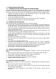
DUNSTABZUGSHAUBE 1 ALLGEMEINES Das von Ihnen gewählte Modell ist eine Dunstabzugshaube für Abluftbetrieb, das auch für Umluftbetrieb verwendbar ist. Eine Haube im ABLUFTBETRIEB saugt den Kochdunst am Entstehungsort an und leitet ihn ins Freie. Für diese Art von Luftreinigung sind keine Kohlefilter notwendig. Eine Haube im UMLUFTBETRIEB saugt den Kochdunst am Entstehungsort an, reinigt ihn durch Kohlefilter und läßt die gereinigte und vom Geruch befreite Luft wieder in denselben Raum zurückströmen.
und das Lokal muß genügend belüftet werden. Im Zweifelsfall geben die nationalen und internationalen gesetzlichen Bestimmungen genaue Informationen über die korrekte Installation von Gasgeräten und des gesamten Lüftungsverbundes der Wohnung, um zu verhindern, daß es zu unvollständigen Verbrennungen kommt, die zu gefährlichen Gasentwicklungen führen könnten (siehe Abb.4). 2.5) Wenn die Dunstabzugshaube im Umluftbetrieb verwendet wird, müssen die Kohlefilter gekauft werden (siehe ZUBEHÖR).
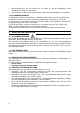
3.3 BEFESTIGUNG AN DER WAND 3.3.1 VORBEREITUNG DER ANSCHLÜSSE DES DEKORSKAMINS Um den Dekorkamin montieren zu können, muß in der Küchendecke ein Anschluß vorgesehen sein. Die Form des Haltebügels ermöglicht eine Verankerung in der Küchendecke und an der Seitenwand (siehe Abb.7).
• • den teleskopischen Teil des Kamins bis zur Stelle, an der der Haltebügel an der Küchendecke montiert ist, ausziehen; die Schrauben auf dem an der Küchendecke-angebrachten Haltebügel fest anschrauben. 3.4 ALLGEMEINE HINWEISE Das Material des Rohrs muß Korrosions und Wärme und Feuerfest sein. Die Herstellerfirma rät dringestens davon ab, Stutzen oder Rohre mit kleinerem Durchmesser als die der Anschlussstelle zu verwenden.
5 BEI REPARATUREN SICHERHEITSMASSNAHMEN ZU BEACHTENDE Reparaturarbeiten und auch die Ersetzung vom Speisekabel dürfen nur von Fachleuten mit genormten Materialien und Geräten durchgeführt werden. Unsachgemäß durchgeführte Reparaturen können Brandgefahr und Stromschläge verursachen. 6 WICHTIGE HINWEISE FÜR DEN SICHEREN GEBRAUCH DES GERÄTES Vor der ersten Inbetriebnahme müssen alle in den vorher beschriebenen Abschnitten der Montageanleitungen genau eingehalten werden.
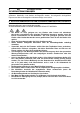
7 BEDIENUNG UND GEBRAUCH In der Abb. 9 finden Sie zwei verschieden Sorten von Bedienungen: Abb.9a SOFT TOUCH Bedienung mit Display und Knöpfe (Sehen Sie Abb.7.1.1). Abb.9b SOFT TOUCH Bedienung mit Ledpunkte und auf EDELSTAHL siebgedruckte Knöpfe (Sehen Sie Abb.7.2.1). 7.1.1 SOFT TOUCH BEDIENUNG MIT DISPLAY UND KNÖPFE (Abb. 9a) Die aktivierte Funktionen sind wie unten gegeben: BELEUCHTUNG: Ein-und Ausschalten der Lampen (Druck weniger als 1 Sekunde).
... um Nachrichte über dem Verschleißstand der Kohlefilter, drücken Sie gleichzeitig die Knöpfe O und +. Auf dem Display erscheint eine Nummer zwischen 0 und 9 inbegriffen. Kleiner ist die Nummer, alter sind die Kohlefilter. 7.1.3 LÖSCHUNG DER FETTFILTER UND KOHLEFILTER ANZEIGE Nachdem Sie die Wartung der Fettfilter gemacht haben, ist es nötig folgendes zu tun: • Motor ausschalten (STOP). • Gleichzeitig für einige Sekunden die Knöpfe O (Null) und T (Timer) drücken .
Wenn die Fettfilter zu reinigen sind, wird ein akustisches Signal ertönt und der Led-punkt auf dem Timer-Knöpf blinkt; wenn Motor ausgeschaltet wird, wird ein akustisches Signal für einige Sekunden ertönt, und der Timer-Knöpf blinkt weiter.
• Wenn die Fettfilter sehr schmutzig sind, kann der Motor nur eine geringe Luftmenge absaugen, daher wird die Funktion des Gerätes vermindert. • Bei zunehmender Sättigung mit fetthaltigen Rückständen erhöht sich außerdem die ENTFLAMMBARKEIT. Die Herstellungsfirma lehnt jegliche Haftung für Brände ab, die durch schlechte Wartung bzw. unterlassene Reinigung der Metall-Fettfilter verursacht worden sind. 8.2 KOHLEFILTER Die Kohlefilter sind Behälter von AKTIVKOHLE, die am Motor angebracht sind.
8.2.2 KOHLE FILTER DIE NICHT REGENERIERBAR SIND ACHTUNG: Für Kohle Filter die nicht regenerierbar sind Wir empfehlen Ersetzung von Kohle-filter nach 200-300 Stunden von Koch-arbeit. KOHLEFILTER KÖNNEN WEDER GEWASCHEN NOCH REGENERIERT WERDEN, SONDERN MUß MAN SIE AUSWECHSELN. Die Kohle-Filter garantieren nicht den Sauerstoffaustausch der Luft.
10 ZUBEHÖR Folgende Sonderzubehöre sind separat erhältlich: • KOHLEFILTER EINMAL VERWENDBAR • KOHELFILTER DIE MAN REGENERIEREN KANN • STARTER SET • ELEKTRISCHE RÜCKSTAUKLAPPE 11 STOERUNGEN Wenn sich die Haube nicht bedienen lässt, machen Sie die Haube für 1 Minute durch Ziehen des Netzsteckers bzw Ausschalten der Sicherung stromlos. Dann schliessen die Haube wieder an.
CAPPA ASPIRANTE 1 GENERALITÀ Il modello da voi scelto è una ASPIRANTE che può anche funzionare da cappa FILTRANTE. Una CAPPA ASPIRANTE preleva l'aria, i fumi ed i vapori di cottura dall'ambiente interno e li riversa all'esterno. Non è necessario l'uso di filtri al carbone per la depurazione. Una CAPPA FILTRANTE preleva l'aria, i fumi ed i vapori di cottura dall'ambiente interno, li depura per mezzo dei filtri al carbone e riversa l'aria depurata nello stesso ambiente.
per evitare che si producano combustioni incomplete con rischio di esalazioni venefiche (FIG.4). 2.5) Se la cappa viene usata come filtrante, occorre acquistare i filtri carbone (VEDI ACCESSORI OPZIONALI). In caso di utilizzo della cappa a muro in versione filtrante, Il flusso d’aria che esce dal camino estetico puo’ essere convogliato verso il basso a causa della presenza di mobili laterali troppo vicini con il rischio di deviare i vapori di cottura.
• • • • • individuate con precisione l’area del soffitto (o della parete) dove applicare la staffa di sostegno per il camino; praticate con il trapano i fori di sostegno e quelli per l’ancoraggio di sicurezza; inserite i tasselli dentro i fori; inserite le viti nei fori del lamierino e nei tasselli; serrate le viti con un cacciavite. 3.3.
In caso di dubbio rivolgersi al personale competente per impianti gas e areazione- 4 INSTALLAZIONE ELETTRICA 4.1 AVVERTENZE L'installazione elettrica può essere fatta solo da personale professionale esperto, qualificato e abilitato dalle leggi vigenti a svolgere tale mansione usando materiali a norma e modalità di installazione a regola d’arte.
5 ATTENZIONI DA SEGUIRE IN CASO DI RIPARAZIONE Le riparazioni, inclusa l’eventuale sostituzione del cavo di alimentazione, vanno effettuate solo da personale qualificato ed abilitato con modalità, strumenti e materiali a norma. Riparazioni fatte da altri possono essere pericolose e dar luogo a folgorazioni e rischi d’incendio. 6 MODALITÀ D'USO e AVVERTENZE IMPORTANTI Prima del primo utilizzo bisogna rispettare tutti i punti dei paragrafi precedenti.
7 FUNZIONAMENTO ED UTILIZZO In FIG. 9 sono riportate le possibili tipologie di comando: FIG.9a comando soft touch con display e tasti FIG.9b comando soft touch con led e tasti serigrafati sull’acciaio; vedi par.7.1.1; vedi par.7.2.1; 7.1.1 COMANDO SOFT TOUCH CON DISPLAY E TASTI (FIG.9a) Le funzioni attivate dai tasti sono elencate qui di seguito: LUCI: O T accende/spegne le lampade (pressione minore di 1 secondo). STOP: arresta il motore.
7.1.3 AZZERAMENTO DEL CONTATORE FILTRI ANTIGRASSO e/o CARBONE Dopo aver effettuato la manutenzione dei filtri, bisogna: • spegnere il motore (posizione di stop); • premere per qualche secondo contemporaneamente i tasti O (zero) e T (timer). A e viene emesso un segnale conferma dell’avvenuto azzeramento compare il simbolo acustico. 7.1.4 IMPOSTAZIONE FUNZIONE FILTRANTE/ASPIRANTE La cappa di serie viene fornita come aspirante (segnalazione solo della lettera F).
Quando i filtri metallici antigrasso sono da pulire, viene emesso un segnale acustico per alcuni secondi ed il led sopra il tasto timer lampeggia; arrestando il motore viene emesso un segnale acustico per alcuni secondi ed il led sopra il tasto timer continua a lampeggiare.
8 MANUTENZIONE 8.1 PULIZIA DEI FILTRI ANTIGRASSO I filtri metallici antigrasso che si trovano sul fondo della cappa, servono per trattenere i grassi che nell’uso normale sono in sospensione nei fumi di cottura, impedendo che si deteriori il motore; possono essere lavati a mano od in lavastoviglie. Per il lavaggio a mano è sufficiente adoperare acqua calda e sapone, spazzolando con forza molte volte e poi risciacquando sotto acqua corrente.
8.2.2 FILTRI CARBONE CHE NON SONO RIGENERABILI ATTENZIONE: (Per Filtri carbone non rigenerabili) Si consiglia di sostituire i filtri carbone dopo circa 200-300 ore di utilizzo del piano cottura. I filtri carbone non possono essere lavati né rigenerati, ma devono essere sostituiti quando si esauriscono. I filtri carbone non garantiscono il ricambio di ossigeno dell’aria.
10 ACCESSORI OPZIONALI Sono disponibili, venduti separatamente, questi accessori opzionali: • FILTRI CARBONE MONO USO • FILTRI CARBONE RIGENERABILI • SET FILTRANTE • VALVOLA DI RITENUTA ELETTRICA 11 GUASTI Se la cappa aspirante non risponde al comando togliere tensione alla cappa per circa 1 minuto estraendo la spina di alimentazione o disinserendo l’interruttore di sicurezza e successivamente ripristinare il collegamento.
COOKER HOOD 1 GENERAL The model you have selected is a decorative suction cooker hood which can also work as filtering hood. A SUCTION HOOD extracts air, fumes and vapours from the inside environment and then expels them outside. It is not necessary to use carbon filters for purifying. A FILTERING HOOD extracts air, fumes and vapours from the inside environment, purifies them by means of carbon filters and then emits the purified air into the same environment.
Wall cooker hood in filtering version: the air flow that comes out can be conveyed to the bottom due to too near side cabinets and the fumes that are taken away from the cooking hob can affect negatively the aspiration flow. This effect can be minimized if both cabinets are exactly at the side of the hood or at a right distance. 3 MOUNTING INSTRUCTIONS ATTENTION! The hood is equipped with standard fixing material.
• • fit the screws in the plateholes and in the plugs; tighten the screws with a screwdriver. 3.3.2 FIXING TO THE WALL To fix the hood to the wall, proceed as follows: • based on the technical drawing, mark the position of the support and safety fixing holes on the wall with a pencil, in such a way that the base of the hood is at the distance from the cooker hob, as indicated in par. (2.1) and that it is horizontal. Mark the position of the holes with a pencil making a small cross on the wall.
4 ELECTRICAL CONNECTION 4.1 WARNING The electrical connection can only be carried out by qualified professional personnel, using standard material and state of the art installation methods. The manufacturer declines any responsibility for installations carried out by unskilled persons and for installations which are not in conformity with the standard norms concerning electrical safety (both concerning methods and materials). 4.
5 PRECAUTIONS TO BE TAKEN IF REPAIRS ARE TO BE CARRIED OUT Repairs, including the replacement of the feed cable if necessary, are to be carried out only by qualified personnel, using standard methods, instruments and materials. Any repairs carried out by others could prove to be dangerous and could be a fire risk. 6 INSTRUCTIONS FOR USE and PRECAUTIONS Before using for the first time, ensure that all the points in the previous paragraphs have been complied with.
7 FUNCTION AND USE In FIG. 9 you see the 2 different kinds of controls: FIG. 9a: soft touch control with display; see par. 7.1.1. FIG. 9b: soft touch control with led points and push buttons screenprinted on s/steel. See par. 7.2.1. 7.1.1 SOFT TOUCH CONTROL WITH DISPLAY AND BUTTONS (FIG. 9a) The activated functions are listed as follows: O T + P LIGHTS: to switch the lights on or off; (pressure inf.
… to find out how clean the fat filters are, press the O and - buttons at the same time. On the display, a number between 0 and 9 will appear, the smaller the number, the dirtier the filter is; … to find out how worn the carbon filters are, press the buttons O and +. On the display, a number between 0 and 9 will appear, the smaller the number, the more worn the filter is. 7.1.
for some seconds and the led point above the timer push button keeps on flashing. When the carbon filters need replacing or regeneration, an acoustic signal is issued for some seconds and the led point above the light push button keeps on flashing. 7.2.3. TO PUT THE GREASE AND CARBON FILTERS CONTROL BACK TO ZERO To put the grease filter counter back to zero you must: • stop the motor; • press the timer push button twice in succession, until you hear the acoustic signal.
8.2 CARBON FILTERS The carbon filters at the suction outlet of the motor, are used to retain the odours of kitchen fumes. It is not necessary to use carbon filters, if the hood is used for suction use. The use of carbon filters is necessary if you use the hood as filtering. We have 2 kinds of carbon filters: Carbon filters that can be regenerated 8.2.1 and Carbon Filters that cannot be regenerated (see 8.2.2). 8.2.
9 CLEANING To preserve the hood in good condition, clean this periodically following the advice given as follows. WARNING! Make sure that power has been completely turned off. The detergent solution recommended is a combination of WATER and NEUTRAL LIQUID SOAP. It is of vital importance that the liquid soap should not contain any grains which could scratch the surface. The solution should be applied first onto a soft cloth which is then rubbed over the shell.
HOTTE ASPIRANTE 1 Généralités Le modèle que vous avez choisi est une hotte ASPIRANTE qui peut aussi avoir la fonction de hotte FILTRANTE. UNE HOTTE ASPIRANTE prélève l'air, les fumées et les vapeurs de cuisson du milieu intérieur et les répand à l'extérieur. L'utilisation des filtres à charbon pour l'épuration n'est pas nécessaire. Une HOTTE FILTRANTE prélève l'air, les fumées et les vapeurs de cuisson du milieu intérieur, les épure par des filtres à charbon et renverse l'air épuré dans le même milieu.
En cas de doute les réglementations nationales et internationales indiquent avec précision les règles de mise en place selon des installations à gaz et le changement de l'air ambiant, pour éviter la production des combustions incomplètes créant le risque d'exhalaisons toxiques (VOIR FIG.4). 2.5) Si la hotte est utilisée comme filtrante il faudra acheter les filtres à charbon (VOIR ACCESSOIRES OPTIONNELS).
3.3.1 PREDISPOSITION DES ATTACHES DE LA CHEMINEE ESTETIQUE Pour pouvoir fixer la cheminée estétique il faut preparer des attaches au plafond. La bride de soutien a une forme qui permet l'ancrage aussi bien au plafond que sur une paroi latérale. (VOIR FIG.7).
3.4 ATTENTION EN GENERAL ! Le tuyau doit être résistant à la chaleur, à la flamme et à la corrosion. La maison productrice déconseille l'usage des tuyaux de diamètre plus petit de celui de sortie de la hotte et des tuyaux en aluminum flexible parce que les performances diminuent. La partie terminale du tuyau, doit avoir une forme appropriée pour éviter que de la pluie, des corps étrangers, ou des souffles de vent entrent dans le tuyau.
5 INSTRUCTIONS A SUIVRE EN CAS DE REPARATION Les réparations y compris le remplacement eventuel du cable d'alimentation doivent être effectuées seulement par le personnel qualifié et titulaire d'un certificat d'aptitude professionnelle avec des modalités, des outils et du matériel aux termes de la loi. Les réparations effectuées par d'autres personnes peuvent être dangereuses et peuvent causer des électrocutions et des risques d'incendie.
7 FONCTIONNEMENT ET EMPLOI Dans la Fig. 9 il y a les differentes possibilités de contrôles: Fig. 9a contrôles soft touch avec display et boutons. Fig. 9b contrôles soft touch avec points de led et boutons serigraphiés sur l’acier. Voir par.7.1.1. Voir par.7.2.1. 7.1.1 CONTROLES SOFT TOUCH AVEC DISPLAY ET BOUTONS (Fig.
… Pour savoir l’état de nettoyage de filtres antigras, appuyer en même temps sur les touches 0 et -. Sur le display il y aura un numéro entre 0 et 9, le plus petit le numéro, le plus le filtre est sale et vice versa. … Pour savoir l’état d’usure de filtres à charbon, appuyer en même temps sur les touches O et +. Sur le display il y aura un numéro entre 0 et 9, le plus petit le numéro, le plus le filtre est usé et vice versa. 7.1.
7.2.2 GESTION AUTOMATIQUE DES FILTRES ANTIGRAS/ CHARBON Les commande électroniques avec leds permettent un contrôle automatique de la gestion des filtres antigras et/ou charbon (seulement dans le cas où la hotte est filtrante), de manière a ce que l’usager puisse éviter de devoir compter le temps passé depuis le dernier entretien.
8 ENTRETIEN 8.1 NETTOYAGE DES FILTRES ANTIGRAS Les filtres antigras qui se trouvent sur le fond de la hotte servent pour retenir les gras qui sont généralement présents dans les fumées de cuisson et pour éviter que le moteur se détériore: il peuvent être lavés à la main ou en lave-vaisselle. Pour le lavage à main, il suffit d’utiliser de l’ eau chaude et du savon, de brosser avec force plusieurs fois et de le rincer avec de l’eau courante.
8.2.2 FILTRES CHARBONS QUI NE SONT PAS REGENERABLE ATTENTION!: POUR LES FILTRES CHARBONS QUI NE SONT PAS REGENERABLE On conseille de remplacer les filtres à charbon après ca 200-300 heures d’usage du plan de cuisson. Les filtres à charbon ne peuvent être lavés ni régenerés, mais ils doivent être remplacés quand il s’ épuisent.Les filtres à charbon ne garantissent pas le recyclage d'oxygène de l'air.
9 NETTOYAGE Pour garder la hotte en bon état, la nettoyer periodiquement en suivant ce qui suit: ATTENTION! Assurez-vous que l'alimentation électrique soit excluse. La substance détergente qu'on vous recommande est une solution d'eau et de SAVON LIQUIDE NEUTRE. Il est très important que le savon liquide soit sans grains qui peuvent érafler la surface. La solution doit être appliquée sur un chiffon moelleux et ensuite on frotte le manteau avec le chiffon.
FILTRANTE FILTERING UMLUFTBETRIEB FILTRANTE 2. 1. ASPIRANTE SUCTION ABLUFTBETRIEB ASPIRANTE 3.
5. 4. 6.
7. = 1 a 3 4 2 1-2-3-4 - 180° b 1 c 3 d 4 2 1-2-3-4 + 180° 8.
0 T 0 T _ _ a a b b + + P 9. 10. 11.
CC-L-412-EL 06067712 13-05-2009