Gas Hob INSTRUCTION BOOK Mod.
☛ For Your Safety These warnings are provided in the interest of safety. You installing or using the appliance. MUST read them carefully before It is most important that this instruction book should be retained with the appliance for future reference. Should the appliance be sold or transferred, always ensure that the book is left with the appliance in order that the new owner can get to know the functions of the appliance and the relevant warnings.
Contents 1. Instruction for the User ............. Pag. 4 5. Electrical Connection ................ Pag. 7 2. Cleaning and Maintenance ....... Pag. 5 6. Adaptation to different types of gas................................ Pag. 8 3. Technical Data ........................... Pag. 6 7. Building In .................................. Pag. 9 4. Instruction for the Installer ....... Pag. 6 1.
2. Cleaning and Maintenance • Disconnect the appliance from the electrical supply, before carrying out any cleaning or manteinance work. Wash the enamelled components with warm soapy water. Never use abrasive cleaners Frequently wash the "caps" and the "crowns" with hot soapy water, carefully taking away any built-up of food. The pan supports are dishwasher proof. If the marks are particularly difficult to remove, use common non-abrasive cleaners or specific products. Never use steel wool pads or acids.
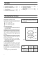
3. Technical Data Gas Burners Rating Rapid Burner (big) Semirapid Burner (medium) Auxiliary Burner (small) Category Setting 2,9 kW 1,9 kW 1 kW II 2ELL 3 B/P Natural Gas 20 mba Gas connection G 1/2" Electric Supply 230 V 50 Hz HOB RECESS DIMENSIONS Length Width 550 mm. 470 mm. 4. Instruction for the Installer ● The side walls of the unit in which the hob is going to be installed, must not exceed the height of the working top.
5. Electrical Connection The appliance is designed to be connected to 230 V monophase electricity supply. The connection must be carried out in compliance with the laws and regulations in force.
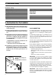
6. Adaptation to different types of gas INJECTORS REPLACEMENT • • • Remove the pan supports. Remove the burner's caps and crowns. With a socket spanner 7 unscrew and remove the injectors (Fig. 6), and replace them with the ones required for the type of gas in use (see table 2). • Reassemble the parts, following the same procedure backwards. • Replace the rating label (placed near the gas supply pipe) with the relevant one for the new type of gas supply.
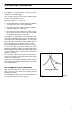
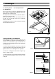
7. Building In A = Auxiliary burner R = Rapid Burner SR = Semirapid burner 0 58 These hobs can be inserted in a built-in kitchen unit whose depth is between 550 and 600 mm. The hobs dimensions are shown in Fig. 9. The edge of the cut out must have a minimum distance from the rear wall of 55 mm. If there are side walls, or sides of the furniture unit near the hob, the cut out edges must have a minimum distance of 100 mm. 51 0 SR A SR R Hanging forniture units or hoods must be placed at 650 mm.
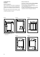
POSSIBILITIES FOR INSERTION Kitchen unit with oven Kitchen unit with door Proper arrangements must be taken in designing the forniture unit, in order to avoid any contact with the bottom of the hob which can be heated when it is operated. The recommended solution is shown in Fig. 11. The panel fitted under the hob should be easily removable to allow an easy access if a technical assistance intervention is needed. The hob recess dimensions must comply the indication given in Figs.