
User manual

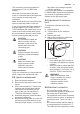


To replace the connection
cable use only H03V2V2-F
T90 or equivalent type.
Make sure that the cable
section is applicable to the
voltage load and the working
temperature. The yellow/
green earth wire (B) must be
approximately 2 cm longer
than the live and neutral wire
(A).
A B
1. Connect the green and yellow (earth)
wire to the terminal which is marked
with the letter 'E', or the earth symbol
, or coloured green and yellow.
2. Connect the blue (neutral) wire to the
terminal which is marked with the
letter 'N' or coloured blue.
3. Connect the brown (live) wire to the
terminal which is marked with the
letter 'L'. It must always be connected
to the network phase. There must be
no cut or stray strands of wire
present. The cord clamp must be
correctly attached to the outer
sheath.
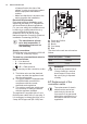
8.8 Building In
min. 600 mm
min. 55 mm
min. 650 mm
560 mm
480 mm
min. 100 mm
30 mm
10 mm
3 mm
11 mm
11 mm
A
A
B
A) supplied seal
B) supplied brackets
CAUTION!
Install the appliance only on
a worktop with flat surface.
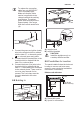
8.9 Possibilities for insertion
The panel installed below the hob must
be easy to remove and let an easy
access in case a technical assistance
intervention is necessary.
Kitchen unit with door
min 20 mm
(max 150 mm)
30 mm
60 mm
B
A
A) Removable panel
B) Space for connections
ENGLISH 15