
User manual


14
490
270
55
40÷50
FO 0959
FO 0954
510
290
FO 0199
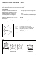
This hob can be inserted in a fitted kitchen unit with a depth of between 550 and 600 mm and having suitable
characteristics.
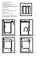
Dimensions (fig. 5)
Fig. 5
The fixture of the hob to the unit must be carried out
as follows:
Position the relevant sealings, supplied, on the edge
of the opening predisposed for installation, taking
care that the edges meet without overlapping. Place
the hob near the opening to permit the connection of
gas and electricity. Install the hob in the opening of
the unit taking care in centring.
Fix the hob with the appropriate clips (Fig. 7).
The traction of the screws is sufficient to trace the
sealing, any excess of which can be removed. The
edge of the hob forms a double labyrinth seal which
provides a total guarantee against the infiltration of
liquids.
If several functions are to be combined (hob 2
burners + long burner + two plates) see figure which
indicates the minimum distance to be observed
between the various openings to be cut on the
surface of the unit.
Installation and assembly
The hob can be installed in a kitchen unit with an
opening for insertion of the dimensions illustrated in
Fig. 6.
Fig. 6 Fig. 7
a) Seal
Back panel
Building In