electrolux
electrolux 3 Welcome to the world of Electrolux Thank you for choosing a first class product from Electrolux, which hopefully will provide you with lots of pleasure in the future. The Electrolux ambition is to offer a wide variety of quality products that make your life more comfortable. You find some examples on the cover in this manual. Please take a few minutes to study this manual so that you can take advantage of the benefits of your new machine.
electrolux Contents For the User Important Safety Information ............................................................................. 5 Operation .......................................................................................................... 7 Using the hob correctly ..................................................................................... 8 Cleaning and Maintenance ................................................................................ 9 European Guarantee .........
electrolux 5 English Important safety information This warnings has been given for the safety of you and others. We therefore ask you to carefully read the procedures of installing and using this cooker. Installation The work of installation must be carried out by competent and qualified installers according to the regulations in force. • Any modifications to the domestic electrical mains which may be necessary for the installation of the appliance should be carried out only by competent personnel.
electrolux • • • • • • appliance. A poor air supply could cause lack of oxygen. Ensure that the gas supply complies with the gas type stated on the identification label, placed near the gas supply pipe. This appliance is not connected to a combustion products evacuation device. It must be installed and connected in accordance with current installation regulations. Particular attention shall be given to the relevant requirements regarding ventilation.
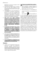
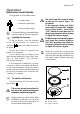
electrolux 7 Operation Hob burner control knobs The symbols on the knobs mean: = no gas supply = maximum gas supply = minimum gas supply For easier lighting, proceed before putting a pan on the pan support. the burners )To Lighting light a burner, turn the relevant knob anticlockwise to maximum position ( ) and push down the knob to ignite. Check the flame is regular and adjust it as required.
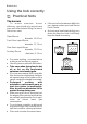
electrolux Using the hob correctly Practical hints The burners To ensure maximum burner efficiency, you should only use pots and pans with a flat bottom fitting the size of the burner used. Rapid Burner diameter 18-26 cm Front Semi-rapid Burner diameter 12-18 cm Rear Semi-rapid Burner diameter 12-22 cm Auxiliary Burner diameter 8-18 cm • For easier lighting, proceed before putting a pan on the pan support. • Use only pans or pots with flat bottom.
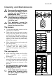
electrolux 9 Cleaning and Mainteinance Disconnect the appliance from the electrical supply, before carrying out any cleaning or manteinance work. The hob is best cleaned whilst it is still warm, as spillage can be removed more easily than if it is left to cool. This appliance cannot be cleaned with steam or with a steam cleaning machine. The burners z z z z The burner caps and crowns can be removed for cleaning.
electrolux The Hob Top z z z Regularly wipe over the hob top using a soft cloth well wrung out in warm water to which a little wasing up liquid has been added. Avoid the use of the following: - household detergent and bleaches; - impregnated pads unsuitable for non-stick saucepans; - steel wool pads; - bath/sink stain removers. Should the hob top become heavily soiled, the following products are recommended: - For stainless steel hobs use a proprietary stainless steel cleaner.
electrolux 11 Technical data Burner gas power Rapid burner Semi-rapid burner Auxiliary burner 3,0 kW 2,0 kW 1,0 kW Category Gas supply Gas connection Electric supply Appliance class II2H3+ gas LPG 28-30 / 37mbar G 1/2" 230 V ~ 50 Hz 3 Hob dimensions Width Depth 594 mm 510 mm Cut out dimensions Width Depth 560 mm 480 mm
electrolux Gas burners BURNER RAPID SEMI-RAPID AUXILIARY TYPE OF GAS POSITION NATURAL GAS 20 mbar VALUE = 37.78 MJ/m3 Ws - 50.7 MJ/ m3 LPG GAS 28-30/37 mbar VALUE = 49.92 MJ/Kg NOMINAL THERMAL POWER kW NOMINAL FLOW RATE m3/h NOZZLE REFERENCE 1/100 mm NOMINAL THERMAL POWER kW NOMINAL FLOW RATE g/h NOZZLE REFERENCE 1/100 mm MAX MIN MAX MIN MAX MIN 3.0 0.75 2.0 0.45 1.0 0.286 0.057 Auxiliary Semi-rapid Rapid 96 Adjust. 70 Adjust. 2.8 2.0 0.45 1.0 0.
electrolux 13 Installation z z z z The following instructions about installation and maintenance must be carried out by qualified personnel in compliance with the regulation in force. The appliance must be electrically disconnected before all interventions. If any electric supply to the appliance is required to carry out the work, ensure all the necessary precautions are followed. The side walls of the unit in which the hob is going to be installed, must not exceed the height of the working top.
electrolux Gas Connection Connection to the gas supply should be with either rigid or semi-rigid pipe, i.e. steel or copper. The connection should be suitable for connecting to RC 1/2 (1/2 BSP male thread). When the final connection has been made, it is essential that a thorough leak test is carried out on the hob and installation. Ensure that the main connection pipe does not exert any strain on the hob.
electrolux 15 • With the aid of a 7mm box spanner the burner injectors can then be unscrewed and replaced by the appropriate Natuaral gas injectors (Fig.1). ) B. Adjustment of minimum level When the hob has been fully installed it will be necessary to check the minimum flame setting. To do this, follow the procedure below. - Turn the gas tap to the MAX position and ignite. - Set the gas tap to the MIN flame position then turn the control knob from MIN to MAX several times.
electrolux screw, until a small regular flame is obtained. If changing from natural gas to LPG, completely tighten clockwise the screw, until a small regular flame is obtained. • Finally check the flame does not go out when quickly turning the knob from the maximum position to the minimum position. This procedure can easily be carried out, anyhow the hob has been positioned or built in the working top.
electrolux 17 Electrical Connection The appliance is designed to be connected to 230 V monophase electricity supply. The connection must be carried out in compliance with the laws and regulations in force.
electrolux Building In SR SR R 51 0 A 594 Fig. 4 A = Auxiliary burner SR= Semi-rapid burner R = Rapid burner Dimensions millimeters are given in These hobs can be inserted in a built-in kitchen unit whose depth is between 550 and 600 mm. The hob dimensions are shown in Fig. 4. The edge of the cut out must have a minimum distance from the rear wall of 55 mm. If there are side walls, or sides of the furniture unit near the hob, the cut out edges must have a minimum distance of 150 mm.
electrolux 19 (Fig.6), taking care that the seals meet without overlapping. 2. Place the hob in the cut out, taking care that it is centred. 3. Fix the hob with the relevant fixing clamps, supplied with the injectors kit (Fig.7). When the screws have been tightened, the excess seal can be removed. The edge of the hob forms a double seal which prevents the ingress of liquids. Fig. 6 a a) seal Fig.
electrolux Possibilities for insertion Kitchen unit with door Proper arrangements must be taken in designing the forniture unit, in order to avoid any contact with the bottom of the hob which can be heated when it is operated. The recommended solution is shown in Fig. 8. The panel fitted under the hob should be easily removable to allow an easy access if a technical assistance intervention is needed. Kitchen unit with oven The hob recess dimensions must comply the indication given in Figs.
electrolux 21 European guarantee This appliance is guaranteed by Electrolux in each of the countries listed at the back of this user manual, for the period specified in the appliance guarantee or otherwise by law.
electrolux
35905-5001 06/08 R.