Gas Hob INSTRUCTION BOOKLET Models EHG 672 - EHG 674 - EHG 675 35670-2601 2 GB
Important Safety Information You MUST read these warnings carefully before installing or using the hob. If you need assistance, contact our Customer Care Department on 01635 522799 Installation ● This hob must be installed by qualified personnel, according to the manufacturer’s instructions and to the relevant British Standards. ● Any gas installation must be carried out by a registered CORGI installer. ● Remove all packaging before using the hob.
Contents For the User For the Installer Description of the Hob Technical Data Page 12 Page 5 Operation Page 6 Important Safety Requirements Page 13 Installation Page 14 Gas Connection Page 14 Building In Page 15 Electrical Connection Page 16 Wiring Diagram Page 17 Fault Finding Page 18 Commissioning Page 20 Servicing Page 21 Conversion from natural gas to LPG Page 21 Maintenance and Cleaning Page 7 Something Not Working? Page 8 Service and Spare Parts Page 8 Guarantee
Description of the Hob 3 1 2 3 EHG 672 4 9 8 7 6 5 3 1 1. 2. 3. 4. 5. 6. 7. 8. 9. Hob Top Rapid Burner Semi-rapid Burners Auxiliary Burner Control knob for back right burner (semi-rapid) Control knob for back left burner (semi-rapid) Control knob for front left burner (rapid) Control knob for front right burner (auxiliary) Electric Ignition Push Button INSTALLATION Any gas installation must be carried out by a registered CORGI installer, and in accordance with existing rules and regulations.
Operation HOB BURNERS To light a burner, turn the relevant control knob anticlockwise to maximum position. At the same time push the electric ignition button which is marked with a little spark.. Then adjust the flame as required. If the burner does not ignite, turn the control knob to zero, and try again. i When switching on the mains, after installation or a power cut, it is quite normal for the spark generator to be activated automatically.
Maintenance and Cleaning Before any maintenance or cleaning can be carried out, you must DISCONNECT the hob from the electricity supply. The hob is best cleaned whilst it is still warm, as spillage can be removed more easily than if it is left to cool. The Hob Top Regularly wipe over the hob top using a soft cloth well wrung out in warm water to which a little wasing up liquid has been added.
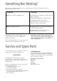
Something Not Working? If the hob is not working correctly, please carry out the following checks before contacting your local Electrolux Service Force Centre. SYMPTOM SOLUTION ■ There is no spark when lighting the gas ◆ Check that the unit is plugged in and the electrical supply is switched on ◆ Check that the RCCB has not tripped (if fitted) ◆ Check the mains fuse has not blown ◆ Check the burner cap and crown have been replaced correctly, e.g. after cleaning.
Guarantee Conditions ELECTROLUX STANDARD GUARANTEE CONDITIONS * Appliances found to be in use within a commercial or similar environment, plus those which are the subject to rental agreements.
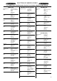
ELECTROLUX SERVICE FORCE To contact your local Electrolux Service Force Centre telephone 0990 929929 CHANNEL ISLANDS GUERNSEY Guernsey Electricity PO Box 4 Vale , Guernsey Channel Islands JERSEY Jersey Electricity Company PO Box 45 Queens Road St Helier Jersey Channel Islands JE4 8NY ISLE OF LEWIS (M69) ABERDEEN (M05) (OWN SALES) BLANTYRE (M07) Unit 5 Block 2 Auchenraith Industrial Estate Rosendale Way Blantyre G72 0NJ (M 67) GLASGOW (M04) 20 Cunningham Road Clyde Estate Rutherglen, Glasgow, G73
ELECTROLUX SERVICE FORCE To contact your local Electrolux Service Force Centre telephone 0990 929929 MIDLANDS BIRMINGHAM (M18) BOURNE (M44) BRIDGNORTH (M72) 66 Birch Road East, Wyrley Road Industrial Estate Witton Birmingham B67DB Manning Road Ind Estate Pinfold Road Bourne PE10 9HT 1 Underhill Street Bridgnorth Salop WV16 4BB LONDON & EAST ANGLIA CANVEY ISLAND 2-4 Sandhurst Kings Road Canvey Island SS8 0QY CHELMSFORD (M47) Hanbury Road Widford Ind Estate Chelmsford Essex CM12 3AE COLINDALE (M53) U
Instructions for the Installer Engineer technical data OVERALL Width: Depth: Height: Weight: DIMENSIONS 580 mm. 500 mm. 88 mm. 8 Kg. SUPPLY CONNECTIONS Gas: RC 1/2 inch (1/2 inch male) Rear right hand corner Electric: 230-240V 50Hz supply, 3 core flexible cable with non rewireable plug fitted with a 3 amp cartridge fuse. CUT OUT DIMENSIONS Width: 550 mm. Depth: 470 mm. Thickness: 30 mm.
Important safety requirements This hob must be installed in accordance with the Gas Safety (Installation and Use) Regulations (Current Edition) and the IEE Wiring Regulations (Current Edition). Detailed recommendations are contained in the following British Standards Codes Of Practice: B.S. 6172/ B.S. 5440, Par. 2 and B.S. 6891 Current Editions. The hob should not be installed in a bed sitting room with a volume of less than 20 m3.
Installation IMPORTANT This hob must be installed by qualified personnel to the relevant British Standards. Any gas installation must be carried out by a registered CORGI installer. The manufacturer will not accept liability, should the above instructions or any of the other safety instructions incorporated in this book be ignored. On the end of the shaft, which includes the GJ 1/2" threaded elbow, adjustment is fixed so that the washer is fitted between the components as shown in the diagram.
Building In Building over a cupboard or drawer ON/OFF SWITCH 2 ON/OFF SWITCH 3 30 1 It is also recommended to carry out the electrical connection to the hob as shown in diagrams 1 and 2. 20 min If the hob is to be installed above a cupboard or drawer it will be necessary to fit a heat resistant board below the base of the hob on the underside of the work surface. a 60 FLEX OUTLET b FLEX OUTLET FO 0763 FO 0764 FO 1013 Dimensions are given in mm.
Electrical connections Any electrical work required to install this hob should be carried out by a qualified electrician or competent person, in accordance with the current regulations. THIS HOB MUST BE EARTHED. The manufacturer declines any liability should these safety measures not be observed. Permanent Connection In the case of a permanent connection, it is necessary that you install a double pole switch between the hob and the electricity supply (mains), with a minimum gap of 3 mm.
Wiring diagram L 1 A 0 2 3 220/240 4 B N A. IGNITOR SWITCH B.
Fault Finding PLUG (with cover removed) Earth Wire Green/Yellow Brown Blue Green Yellow START Isolate appliance and carry out: A: Earth Continuity check. Neutral Wire Blue SOCKET (face view) ( ) E( ) FUSE Preliminary Electrical Systems Check N L Blue Brown Green Yellow NO YES Carry out: C: Polarity check. Has inlet fuse blown? NO YES Carry out: D: Resistance to Earth check. Electricity supply should now be satisfactory. A.
Ignition System / Gas Ignition Ignitor does not spark YES Check gas supply at burner NO Check plug top fuse and replace if necessary Light burner manually Check polarity and earth continuity of supply point Check by pass simmer adjusted Check position of the electrode Check earth continuity of appliance Check continuity from 'N' on the mains connector block and "O" on the ignitor unit Check continuity from the tip of each electrode to the terminals 1 to 4 on the ignitor unit Check continuity fro
Commissioning When the hob has been fully installed it will be necessary to check the minimum flame setting. To do this, follow the procedure below. - Turn the gas tap to the MAX position and ignite. - Set the gas tap to the MIN flame position then turn the control knob from MIN to MAX several times. If the flame is unstable or is extinguished follow the procedure below. Procedure: ☞ Re-ignite the burner and set to MIN. Remove the control knob.
Servicing A: Removal Of Hob Top 1. Remove all control knobs, pan supports, burner caps and crowns. 2. Remove 2 screws from each burner. 3. Lift the hob top at the rear and disengage it from the front locators. 4. Remove fixing nut from generator and earth lead to hob. 5. Reassemble in reverse order ensuring leads are not trapped below the hob top (rewire as wiring diagram). B: Removal Of the Hob Taps (Isolate Electric Supply) 1. Follow the procedures in Section A. 2.