Gas hob INSTR UCTION BOOKLET INSTRUCTION Please read this instruction booklet before using the appliance Mod.
Important Safety Information You MUST read these warnings carefully before installing or using the hob. If you need assistance, contact our Customer Care Department on 08705 950 950 Installation z z z z z This appliance must be installed and serviced by a competent person as stated in the Gas Safety ( Installation and Use) Regulations Current Editions and the IEE Wiring Regulations. For appliances installed in the Republic of Ireland please refer to NSAI-Domestic Gas Installations I.S.
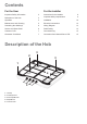
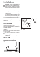
Contents For the Installer For the User Important Safety Information 2 Instructions for the Installer 8 Description of the Hob 3 Important safety requirements 9 Operation 4 Installation 10 Maintenance and Cleaning 5 Electrical connections 12 Something Not Working? 6 Wiring Diagram 13 Service and Spare Parts 6 Fault Finding 13 Customer Care 7 Commissioning 15 Guarantee Conditions 7 Conversion from Natural Gas to LPG 15 Description of the Hob 3 2 3 1 4 5 1. 2. 3. 4. 5.
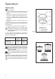
Operation Hob burners ) To light a burner: z turn the relevant control knob anticlockwise to the maximum position, then push it down to ignite the burner; z upon ignition, keep the knob pushed down about 5 seconds. This will allow the "thermocouple" (Fig. 1, lett. D) to be heated and the safety device to be switched off, otherwise the gas supply would be interrupted. z then, check the flame is regular and adjust it as required.
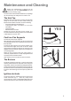
Maintenance and Cleaning Before any maintenance or cleaning can be carried out, you must DISCONNECT the hob from the electricity supply. The hob is best cleaned whilst it is still warm, as spillage can be removed more easily than if it is left to cool. The Hob Top Regularly wipe over the hob top using a soft cloth well wrung out in warm water to which a little washing up liquid has been added.
Something Not Working? If the hob is not working correctly, please carry out the following checks before contacting your local Electrolux Service Force Centre. IMPORTANT: If you call out an engineer to a fault listed below, or to repair a fault caused by incorrect use or installation, a charge will be made even if the appliance is under guarantee.
Customer Care Department For general enquiries concerning your Electrolux appliance or for further information on Electrolux products, please contact our Customer Care Department by letter or telephone at the address below or visit our website at www.electrolux.co.uk Customer Care Department Electrolux 55-77 High Street Slough Berkshire SL1 1DZ Tel. 08705 950950 (*) * calls to this number may be recorded for training purposes.
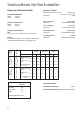
Instructions for the Installer Engineers technical data Ignition HT Spark Overall dimensions Spark Generator Ispra Control's BF 50046-06 230-240V 0.6 VA T 120 Spark Gap Fixed Width: Depth: 580 mm 510 mm Cut out dimensions Width: Depth: 560 mm 480 mm Supply connections Gas: RC 1/2 inch (1/2 inch male) Rear right hand corner Burner VALUE = 37.78 MJ/m3 Characteristics Ws - 50.7 MJ/ m3 VALUE = 49.
Important safety requirements This hob must be installed in accordance with the Gas Safety (Installation and Use) Regulations (Current Edition) and the IEE Wiring Regulations (Current Edition). For appliances installed in the Republic of Ireland please refer to NSAI- Domestic Gas Installation I.S. 813 Current Editions and the ETCI Rules for Electrical Installations. Provision for ventilation Detailed recommendations are contained in the following British Standards Codes Of Practice: B.S. 6172/ B.S.
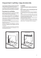
Installation IMPORTANT: This hob must be installed by a competent person to the relevant Gas Standards. Please, ensure that, once the hob is installed, it is easily accessible for the engineer in the event of a breakdown. WHEN THE HOB IS FIRST INSTALLED Once the hob has been installed, it is important to remove any protective materials, which were put on in the factory. Any gas installation must be carried out by a competent person.
Building In Building over a cupboard or drawer If the hob is to be installed above a cupboard or drawer it will be necessary to fit a heat resistant board below the base of the hob on the underside of the work surface. 1 ON/OFF SWITCH 2 It is also recommended to carry out the electrical connection to the hob as shown in diagrams 1 and 2. 3 ON/OFF SWITCH FLEX OUTLET FLEX OUTLET FO 2564 FO 0763 FO 2044 Dimensions are given in mm.
Electrical connections Any electrical work required to install this hob should be carried out by a qualified electrician or competent person, in accordance with the current regulations. THIS HOB MUST BE EARTHED. The manufacturer declines any liability should these safety measures not be observed. This hob is designed to be connected to a 230-240 V 50 Hz AC electrical supply. Before switching on, make sure the electricity supply voltage is the same as that indicated on the hob rating plate.
Wiring Diagram N 1. TAPS IGNITOR SWITCHES 220 240 2. IGNITOR UNIT 1 2 3 0 4 2 1 L Fault Finding Preliminary Electrical Systems Check Blue START Isolate appliance and carry out: A: Earth Continuity check. Blue Brown Neutral Wire Blue E( ) FUSE Brown SOCKET (face view) PLUG (with cover removed) Earth Wire ( ) Green/Yellow N L Green Yellow YES NO Carry out: C: Polarity check. Has inlet fuse blown? YES NO Inlet wiring faulty. Rectify any fault.
Ignition System / Gas Ignition Ignitor does not spark YES Check gas supply at burner NO Check plug top fuse and replace if necessary Light burner manually Check by pass simmer Check polarity and earth continuity of supply point Check position of the electrode Check earth continuity of appliance Check continuity from 'N' on the mains connector block and "O" on the ignitor unit Check continuity from 'L' on the mains connector block and the taps ignition switches Check continuity from ignition swit
Commissioning When the hob has been fully installed it will be necessary to check the minimum flame setting. To do this, follow the procedure below. - Turn the gas tap to the MAX position and ignite. - Set the gas tap to the MIN flame position then turn the control knob from MIN to MAX several times. If the flame is unstable or is extinguished follow the procedure below. ) - - Re-ignite the burner and set to MIN.
CUSTOMER CARE Electrolux 55-77 High Street Slough Berkshire, SL1 1DZ Tel: 08705 950950 © Electrolux plc 2003 The Electrolux Group. The world’s No.1 choice. 07/04 Grafiche MDM - Forlì The Electrolux Group is the world’s largest producer of powered appliances for kitchen, cleaning and outdoor use. More than 55 million Electrolux Group products (such as refrigerators, cookers, washing machines, vacuum cleaners, chain saws and lawn mowers) are sold each year to a value of approx.