Gas hobs INSTRUCTION BOOKLET Please read this instruction booklet before using the appliance Mod.
Important Safety Information You MUST read these warnings carefully before installing or using the hob. If you need assistance, contact our Customer Care Department on 08705 950950 Installation l l l l l This hob must be installed by qualified personnel, according to the manufacturers instructions and to the relevant British Standards. Any gas installation must be carried out by a registered CORGI installer. Remove all packaging before using the hob.
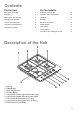
Contents For the User For the Installer Description of the Hob 3 Engineers technical data Operation 4 Important safety requirements 10 Maintenance and Cleaning 4 Installation 10 Something Not Working? 5 Building In 11 Service and Spare Parts 5 Electrical connections 12 Customer Care Department 6 Wiring diagram 13 Guarantee Conditions 6 Fault finding 13 Commissioning 15 Conversion from natural gas to LPG 15 9 Description of the Hob 3 2 3 1 4 1. 2. 3. 4. 5. 6. 7. 8. 9.
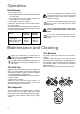
Operation Hob Burners F To light a burner: push the electric ignition pushbutton which is marked by a little spark; l at the same time turn the relevant control knob anticlockwise to maximum position; l then adjust the flame as required. If the burner does not ignite, turn the control knob to zero, and try again. To ensure maximum burner efficiency, you should only use pots and pans with a flat bottom fitting the size of the burner used (see table).
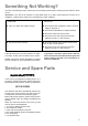
Something Not Working? If the hob is not working correctly, please carry out the following checks before contacting your local Service Force Centre. IMPORTANT: If you call out an engineer to a fault listed below, or to repair a fault caused by incorrect use or installation, a charge will be made even if the appliance is under guarantee.
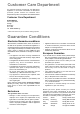
Customer Care Department For general enquiries concerning your Electrolux appliance or for further information on Electrolux products, please contact our Customer Care Department by letter or telephone at the address below Customer Care Department ELECTROLUX 55-77 High Street Slough Berkshire SL1 1DZ Tel. 08705 950950 (*) * calls to this number may be recorded for training purposes.
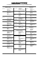
To contact your local Service Force Centre telephone 08705 929 929 NORTH EAST CHANNEL ISLANDS ISLE OF LEWIS GUERNSEY Guernsey Electricity PO Box 4 Vale, Guernsey Channel Islands GY1 3AD KELSO Jersey Electricity Company Haut De L’orme Rue De Haut De L’orme Trinity Jersey Channel Islands JE3 5FG ORKNEY JERSEY 2, 6 & 8 Woodmarket Kelso Borders TD5 7AX 7 King Street Kirkwall Orkney KW15 1JF SCOTLAND ABERDEEN 54 Claremont Street Aberdeen AB10 6RA AUCHTERMUCHTY 33a Burnside Auchtermuchty Fife KY14 7AJ B
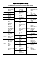
To contact your local Service Force Centre telephone 08705 929 929 LONDON & EAST ANGLIA MIDLANDS BIRMINGHAM 66 Birch Road East Wyrley Trading Estate Witton Birmingham B6 7DB BOURNE Pinfold Road Bourne PE10 9HT BRIDGNORTH 68 St.
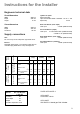
Instructions for the Installer Engineers technical data Overall dimensions Width Depth Height Ignition HT Spark Spark Generator Ispra Control's BF 50046 - 230-240V 0.6 YA T 120 Spark Gap Fixed 580 mm. 500 mm. 8 mm. Cut out dimensions Width Depth Thickness Rear Left Burner (semi rapid) Heat Input 2.0 kW (6824 BTU/HR) 550 mm. 470 mm. 30 mm. Front Left Burner (rapid) Heat Input 3.0 kW Natural Gas (10236 BTU/HR) 2.8 kW L.P.G. (9554 BTU/HR) Supply connections Rear Right Burner (semi rapid) Heat Input 2.
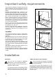
Important safety requirements This hob must be installed in accordance with the Gas Safety (Installation and Use) Regulations (Current Edition) and the IEE Wiring Regulations (Current Edition). Detailed recommendations are contained in the following British Standards Codes Of Practice: B.S. 6172/ B.S. 5440, Part 2 and B.S. 6891 Current Editions. The hob should not be installed in a bed sitting room with a volume of less than 20 m3.
Gas Connection Connection to the gas supply should be with either rigid or semi-rigid pipe, i.e. steel or copper. The connection should be suitable for connecting to RC 1/2 (1/2 BSP male thread). When the final connection has been made, it is essential that a thorough leak test is carried out on the hob and installation. Ensure that the main connection pipe does not exert any strain on the hob. FO 0814 A)End of shaft with nut B)Washer C)Elbow FO 0264 Rectangular cut-out size for hob 55 m in.
Fitting the Hob into the worktop Carry out the building in of the hob as follows: put the seals supplied with the hob, on the edges of the cut out: place them exactly on the front and rear edge and at 50 mm. from the side edges, taking care that the seals meet without overlapping; place the hob in the cut out, taking care that it is centred; fix the hob with the relevant fixing clamps and screws, as shown in the diagram. When the screws have been tightened, the excess seal can be removed.
Wiring diagram L 1 A 0 2 3 220/240 A. IGNITOR SWITCH 4 B. IGNITOR UNIT B N Fault finding Preliminary Electrical Systems Check Green Yellow START Isolate appliance and carry out: A: Earth Continuity check. Earth Wire Green/Yellow ( ) Neutral Wire Blue N Blue Brown E( ) FUSE Brown Blue SOCKET (face view) PLUG (with cover removed) L Green Yellow NO YES Carry out: C: Polarity check. Has inlet fuse blown? YES NO Inlet wiring faulty. Rectify any fault.
Ignition System / Gas Ignition Ignitor does not spark YES Check gas supply at burner NO Check plug top fuse and replace if necessary Light burner manually Check polarity and earth continuity of supply point Check by pass simmer adjusted Check position of the electrode Check earth continuity of appliance Check continuity from 'N' on the mains connector block and "O" on the ignitor unit Check continuity from 'L' on the mains connector block and the taps ignition switches Check continuity from igni
Commissioning When the hob has been fully installed it will be necessary to check the minimum flame setting. To do this, follow the procedure below. - Turn the gas tap to the MAX position and ignite. - Set the gas tap to the MIN flame position then turn the control knob from MIN to MAX several times. If the flame is unstable or is extinguished follow the procedure below. Procedure: F Re-ignite the burner and set to MIN. Remove the control knob.
Grafiche MDM - Forlì CUSTOMER CARE Electrolux 55-77 High Street Slough Berkshire, SL1 1DZ Tel: 08705-950950 © Electrolux Household Appliances Limited 2000 The Electrolux Group. The worlds No.1 choice. The Electrolux Group is the worlds largest producer of powered appliances for kitchen, cleaning and outdoor use. More than 55 million Electrolux Group products (such as refrigerators, cookers, washing machines, vacuum cleaners, chain saws and lawn mowers) are sold each year to a value of approx.