
User manual

11
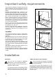
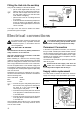
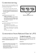
It is important to install the elbow correctly, with
the shoulder on the end of the thread, fitted to
the hob connecting pipe.
Failure to ensure the correct assembly will cau-
se leakage of gas.
Gas Connection
Connection to the gas supply should be with either
rigid or semi-rigid pipe, i.e. steel or copper.
The connection should be suitable for connecting to
RC 1/2 (1/2 BSP male thread).
When the final connection has been made, it is
essential that a thorough leak test is carried out on the
hob and installation.
Ensure that the main connection pipe does not exert
any strain on the hob.
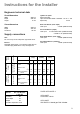
Cut Out Size
The dimensions of the cut-out are given in the
diagram.
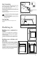
Building In
Building over a cupboard or
drawer
If the hob is to be installed above a cupboard or
drawer it will be necessary to fit a heat resistant
board below the base of the hob on the underside
of the work surface.
It is also recommended to carry out the electrical
connection to the hob as shown in diagrams 1 and
2.
Building over a kitchen unit
with door
Proper arrangements must be taken in designing
the furniture unit, in order to avoid any contact with
the bottom of the hob which can be heated when it
is operated. The recommended solution is shown
in diagram 3.
The panel fitted under the hob ("a") should be easily
removable to allow easy access if technical
assistance is needed. The space behind the kitchen
unit ("b") can be used for connections.
A)End of shaft with nut
B)Washer
C)Elbow
FO 0814
FO 0264
Rectangular cut-out size for hob
550
470
55 min.
30
FO 2098
Dimensions are given in mm.
ON/OFF SWITCH
FLEX
OUTLET
FO 0763
1
ON/OFF SWITCH
FLEX
OUTLET
FO 0764
2
Dimensions are given in mm.
30
20 min
60
a
b
FO 1013
3