Gas hobs INSTRUCTION BOOKLET Please read this instruction booklet before using the appliance Mod.
Important Safety Information You MUST read these warnings carefully before installing or using the hob. If you need assistance, contact our Customer Care Department on 08705 950950 Installation This hob must be installed by qualified personnel, according to the manufacturer’s instructions and to the relevant British Standards. Any gas installation must be carried out by a registered CORGI installer. Remove all packaging before using the hob.
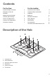
Contents For the User For the Installer Important Safety Information 2 Instructions for the Installer 8 Description of the Hob 3 Important safety requirements 9 Operation 4 Installation 9 Maintenance and Cleaning 4 Building In 10 Something Not Working? 5 Electrical connections 11 Service and Sparte Parts 6 Wiring Diagram 12 Customer Care Department 6 Fault Finding 12 Guarantee Conditions 7 Commissioning 14 Conversion from Natural Gas to LPG 15 Description of the Hob 2 1
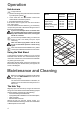
Operation Hob burners To light a burner: push the electric ignition push-button which is marked by a little spark symbol ( ); at the same time turn the relevant control knob anticlockwise to maximum position; then adjust the flame as required. If the burner does not ignite, turn the control knob to zero, and try again. To ensure maximum burner efficiency, you should only use pots and pans with a flat bottom fitting the size of the burner used (see table).
Pan Supports and Wok Stand To keep the pan supports in the correct position, they are hooked into hinges at the back of the hob. The pan supports can be lifted for easier cleaning, as shown in Fig. 1. To remove the pan supports completely, proceed as shown in Fig. 2. The pan supports and the Wok Stand are dishwasher proof. If washing them by hand, take care when drying them as the enamelling process occasionally leaves rough edges. If necessay, remove stubborn stains using a paste cleaner.
Service and Spare Parts In the event of your appliance requiring service, or if you wish to purchase spare parts, please contact your local Electrolux Service Force Centre by telephoning: 0870 5 929929 Your telephone call will be automatically routed to the Service Force Centre covering your post code area. For the address of your local Service Force Centre and further information about Service Force, please visit the website at www.serviceforce.co.
Guarantee Conditions Electrolux Guarantee conditions We, Electrolux, undertake that if, within 12 months of the date of the purchase, this Electrolux appliance or any part thereof is proved to be defective by any reason only of faulty workmanship or materials, we will, at our option, repair or replace the same FREE OF ANY CHARGE for labour, materials or carriage on condition that: * The appliance has been correctly installed and used only on the gas and electricity supply stated on the rating plate.
Instructions for the Installer Engineers technical data Ignition HT Spark Spark Generator OVERALL DIMENSIONS Width: Depth: Spark Gap 680 mm. 510 mm. Rear Left Burner (semi rapid) Heat Input 2.0 kW (6824 BTU/HR) CUT OUT DIMENSIONS Width: Depth: Front Left Burner (auxiliary) Heat Input 1.0 kW (3413 BTU/HR) 560 mm. 480 mm. Rear Right Burner (semi rapid) Heat Input 2.0 kW (6824 BTU/HR) SUPPLY CONNECTIONS Gas: R 1/2 inch (1/2 inch male) Rear right hand corner Front Right Burner (rapid) Heat Input 3.
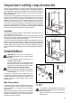
Important safety requirements This hob must be installed in accordance with the Gas Safety (Installation and Use) Regulations (Current Edition) and the IEE Wiring Regulations (Current Edition). Detailed recommendations are contained in the following British Standards Codes Of Practice: B.S. 6172/ B.S. 5440, Part 2 and B.S. 6891 Current Editions. The hob should not be installed in a bed sitting room with a volume of less than 20 m3.
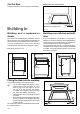
Cut Out Size Rectangular cut-out size for hob 480 The dimensions of the cut-out are given in the diagram. 560 150 min Dimensions are given in mm. Building In FO 2038 Building over a cupboard or drawer Building over a kitchen unit with door If the hob is to be installed above a cupboard or drawer it will be necessary to fit a heat resistant board below the base of the hob on the underside of the work surface.
Seal a FO 0199 Electrical connections Any electrical work required to install this hob should be carried out by a qualified electrician or competent person, in accordance with the current regulations. The manufacturer declines any liability should these safety measures not be observed. Permanent Connection In the case of a permanent connection, it is necessary that you install a double pole switch between the hob and the electricity supply (mains), with a minimum gap of 3 mm.
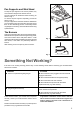
Wiring Diagram L A. IGNITOR SWITCH 1 A B. IGNITOR UNIT 2 0 3 220/240 4 5 6 B N Fault Finding Brown Blue Green Yellow Earth Wire Green/Yellow START Isolate appliance and carry out: A: Earth Continuity check. SOCKET (face view) PLUG (with cover removed) Neutral Wire Blue ( ) E( ) FUSE Preliminary Electrical Systems Check N L Blue Brown Green Yellow YES NO Carry out: C: Polarity check. Has inlet fuse blown? NO YES Inlet wiring faulty. Rectify any fault.
Ignition System / Gas Ignition Ignitor does not spark YES Check gas supply at burner NO Check plug top fuse and replace if necessary Light burner manually Check polarity and earth continuity of supply point Check by pass simmer adjusted Check position of the electrode Check earth continuity of appliance Check continuity from 'N' on the mains connector block and "O" on the ignitor unit Check continuity from 'L' on the mains connector block and the taps ignition switches Check continuity from igni
Commissioning When the hob has been fully installed it will be necessary to check the minimum flame setting. To do this, follow the procedure below. - Turn the gas tap to the MAX position and ignite. - Set the gas tap to the MIN flame position then turn the control knob from MIN to MAX several times. If the flame is unstable or is extinguished follow the procedure below. Procedure: Re-ignite the burner and set to MIN. Remove the control knob.
Conversion from Natural Gas to LPG It is important to note that this model is designed for use with natural gas but can be converted for use with butane or propane gas providing the correct injectors are fitted. The gas rate is adjusted to suit. Method • • • • Ensure that the gas taps are in the 'OFF' position Isolate the hob from the electrical supply Remove all pan supports, burner caps, rings, crowns and control knobs.
Grafiche MDM - Forlì CUSTOMER CARE Electrolux 55-77 High Street Slough Berkshire, SL1 1DZ Tel: 08705-950950 © Electrolux plc 2003 The Electrolux Group. The world’s No.1 choice. The Electrolux Group is the world’s largest producer of powered appliances for kitchen, cleaning and outdoor use. More than 55 million Electrolux Group products (such as refrigerators, cookers, washing machines, vacuum cleaners, chain saws and lawn mowers) are sold each year to a value of approx.