instruction booklet GB gas hob EHG 7812 EHG 7822
electrolux
electrolux 3 Welcome to the world of Electrolux Thank you for choosing a first class product from Electrolux, which hopefully will provide you with lots of pleasure in the future. The Electrolux ambition is to offer a wide variety of quality products that make your life more comfortable. You find some examples on the cover in this manual. Please take a few minutes to study this manual so that you can take advantage of the benefits of your new machine.
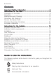
electrolux Contents Important Safety Information ......................................................... 5 Instructions for the User ................................................................ 9 Description of the Hobs ......................................................................... 8 Operation ............................................................................................ 10 Maintenance and Cleaning .................................................................
electrolux 5 Important Safety Information You MUST rread ead these war nings car efully befor e installing or carefully before using the hob. If you need assistance, contact our Customer Care Department on 08705 950950 I nstallation # # # # # This appliance must be installed and serviced by a competent person as stated in the Gas Safety (Installation and Use) Regulations Current Editions and the IEE Wiring Regulations.
electrolux # # # # # # # # # When using the hob for a long period time, the ventilation should be improved, by opening a window or increasing the extractor speed. Do not use this hob if it is in contact with water. Do not operate the hob with wet hands. Ensure the control knobs are in the ‘OFF’ position when not in use. When using other electrical appliances, ensure the cable does not come into contact with the hot surfaces of the cooking appliance.
electrolux 7 Information "AfterEnvironmental installation, please dispose of the packaging with due regard to # safety and the environment. # When disposing of an old appliance, make it unusable, by cutting off the cable. # The symbol on the product or on its packaging indicates that this product may not be treated as household waste. Instead it shall be handed over to the applicable collection point for the recycling of electrical and electronic equipment.
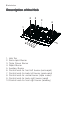
electrolux Description of the Hob 2 2 3 4 1 67 5 89 10 1. Hob Top 2. Semi-rapid Burner 3. Triple Crown Burner 4. Rapid Burner 5. Auxiliary Burner 6. Control knob for front left burner (semi-rapid) 7. Control knob for back left burner (semi-rapid) 8. Control knob for central burner (triple crown) 9. Control knob for back right burner (rapid) 10.
electrolux 9 INSTALLATION Any gas installation must be carried out by a registered competent person, and in accordance with existing rules and regulations. The relevant instructions are to be found in the second section of this manual. Please, ensure that, once the hob is installed, it is easily accessible for the engineer in the event of a breakdown. WHEN THE HOB IS FIRST INSTALLED Once the hob has been installed, it is important to remove any protective materials, which were put on in the factory.
electrolux Operation Hob burners control knobs The symbols on the knobs mean that : # there is no gas supply there is maximum gas supply there is minimum gas supply Lighting the burners For easier lighting, proceed before putting a pan on the pan support. ! To light a burner: # push in the relevant control knob and turn it anticlockwise to maximum position ( ), to ignite the burner. Only for model EHG 7822 # Upon ignition, keep the knob pushed down about 5 seconds seconds.
electrolux 11 Using the hob correctly To ensure maximum burner efficiency, it is strongly recommended that you use only pots and pans with a flat bottom fitting the size of the burner used, so that flame will not spread beyond the bottom of the vessel (see the table beside).
electrolux Maintenance and Cleaning Before any maintenance or cleaning can be carried out, you must DISCONNECT the hob fr om the electricity supply from supply.. The hob is best cleaned whilst it is still warm, as spillage can be removed more easily than if it is left to cool. This appliance cannot be cleaned with steam or with a steam cleaning machine. The Hob T op Top Regularly wipe over the hob top using a soft cloth well wrung out in warm water to which a little wasing up liquid has been added.
electrolux 13 The Burners The burner caps and crowns can be removed for cleaning. Wash the burners caps and crowns using hot soapy water, and remove marks with a mild paste cleaner. A well moistened soap impregnated steel wool pad can be used with caution, if the marks are particularly difficult to remove. After cleaning, be sure to wipe dry with a soft cloth. The Ignition electrode The electric ignition is obtained through a ceramic electrode which contains a metal electrode (Fig. 1 - C).
electrolux Something Not W orking? Working? If the hob is not working correctly, please carry out the following checks before contacting your local Service Force Centre. SYMPTOM % There is no spark when lighting the gas. SOLUTION & & & & % The gas ring burns unevenly. & & Check that the unit is plugged in and the electrical supply is switched on. Check that the RCCB has not tripped (if fitted). Check the mains fuse has not blown. Check the burner cap and crown have been replaced correctly, e.
electrolux 15 Instructions for the Installer Engineer technical data OVERALL DIMENSIONS Width: Depth: 744 mm 510 mm CUT OUT DIMENSIONS Width: Depth: 560 mm 480 mm SUPPL Y CONNECTIONS SUPPLY Gas: R 1/2 inch (1/2 inch male) Rear right hand corner Electric: 230 V~ 50 Hz supply, 3 core flexible cable with non rewireable plug fitted with a 3 amp cartridge fuse HEA T INPUT HEAT Rear Left Burner (semi rapid) Front Left Burner (semi rapid) Rear Right Burner (rapid) Central Burner (triple crown) Front Right B
electrolux BURNER RAPID POSITION M A X MIN SEMI-RAPID A U X I L I A R Y TRIPLECROWN TYPE OF GAS NATURAL GAS 20 mbar VALUE = 37.78 MJ/m 3 Ws - 50.7 MJ/ m3 LPG GAS 28-30/37 mbar VALUE = 49.92 MJ/Kg NOMINALTHERMAL POWER kW NOMINALFLOW RATE m3/h 3.0 0.75 M A X MIN 2.0 M A X MIN 0.45 1.0 MAX MIN 0.33 4.0 1.2 0.286 0.057 0.190 0.038 0.095 0.028 0.381 0.114 119 Adjust. 96 Adjust. 70 Adjust. 146 Adjust. NOMINALTHERMAL POWER kW 2.8 0.75 2.0 0.45 1.0 0.33 4.0 1.
electrolux 17 Important safety requirements This hob must be installed in accordance with the Gas Safety (Installation and Use) Regulations (Current Edition) and the IEE Wiring Regulations (Current Edition). For appliances installed in the Republic of Ireland please refer to NSAI- Domestic Gas Installation I.S. 813 Current Editions and the ETCI Rules for Electrical Installations.
electrolux CLEARANCES REQUIRED WHEN FITTING THE GAS HOB WITHOUT A COOKER HOOD ABOVE CLEARANCES REQUIRED WHEN FITTING THE GAS HOB WITH A COOKER HOOD ABOVE 600 mm 600 mm 700 mm 700 mm 400 mm 400 mm 55 100 mm mm 55 400 mm mm 400 mm 50 m 100 m 50 m m mm 50 m m 50 m m Installation IMPOR TANT This hob must be installed by a competent person to the relevant Gas Standards. Any gas installation must be carried out by a registered competent person.
electrolux 19 On the end of the shaft, which includes the G 1/2" threaded elbow, adjustment is fixed so that the washer is fitted between the components as shown in the diagram. Screw the parts together without using excessive force. FO 0814 FO 0264 A) End of shaft with nut B) Washer C) Elbow Gas Connection Connection to the gas supply should be with either rigid or semi-rigid pipe, i.e. steel or copper. The connection should be suitable for connecting to R 1/2 (1/2 BSP male thread).
electrolux Cut Out Size The dimensions of the cut-out are given in the diagram.
electrolux 21 Building In B uilding over a cupboard or drawer If the hob is to be installed above a cupboard or drawer it will be necessary to fit a heat resistant board below the base of the hob on the underside of the work surface. It is also recommended to carry out the electrical connection to the hob as shown in diagrams 1 and 2.
electrolux Fitting the Hob into the Worktop Carry out the building in of the hob as follows: 1. place the seals supplied with the hob on the front edge of the cut out. Then, place them at 86 mm from the side edges and at 10 mm from the rear edge, as shown in the diagram, taking care that the seals meet without overlapping. 2. Place the hob in the cut out, taking care that it is centred. 3. Fix the hob with the relevant fixing clamps, supplied with the injectors kit (see diagram).
electrolux 23 Electrical Connections Any electrical work required to install this hob should be carried out by a qualified electrician or competent person, in accordance with the current regulations. THIS HOB MUST BE EARTHED. The manufacturer declines any liability should these safety measures not be observed. This hob is designed to be connected to a 230 V 50 Hz AC electrical supply. Before switching on, make sure the electricity supply voltage is the same as that indicated on the hob rating plate.
electrolux The replacement of electric cable must be carried out exclusively by the service force centre or by personnel with similar competencies, in accordance with the current regulations.
electrolux 25 Wiring Diagram
electrolux Fault Finding Preliminary Electrical Systems Check Blue Brown START Isolate appliance and carry out: A: Earth Continuity check. YES NO Green Yellow Blue Green Yellow Brown Carry out: C: Polarity check. Carry out: D: Resistance to Earth check. Has inlet fuse blown? Electricity supply should now be satisfactory. YES NO PLUG (with cover removed) Earth Wire Green/Yellow Neutral Wire Blue SOCKET (face view) ( ) E( ) FUSE Inlet wiring faulty. Rectify any fault.
electrolux 27 A. EARTH CONTINUITY CHECK Appliance must be electrically disconnected - meter set on W (Ohms) x 1 scale and adjust zero if necessary. — Test leads from any appliance earth point to earth pin on plug. Resistance should be less than 0.1 W (Ohm), check all earth wires for continuity and all contacts clean and tight. B. INSULA TION CHECK INSULATION Appliance electrically disconnected, all switches ON. a) meter set on W (Ohms) x 1 scale. Test leads from L to N in appliance terminal block.
electrolux Ignition System / Gas Ignition Ignitor does not spark YES Check gas supply at burner NO Check plug top fuse and replace if necessary Check polarity and earth continuity of supply point Check earth continuity of appliance Check continuity from 'N' on the mains connector block and "O" on the ignitor unit Check continuity from 'L' on the mains connector block and the taps ignition switches Check continuity from ignition switches connector to ignitor unit Light burner manually Check by
electrolux 29 Commissioning When the hob has been fully installed it will be necessary to check the minimum flame setting. To do this, follow the procedure below. the gas tap to the MAX position and ignite. ! 1)2) Turn Set the gas tap to the MIN flame position then turn the control knob from MIN to MAX several times. If the flame is unstable or is extinguished follow the procedure below. Procedure: the burner and set ! 1) Re-ignite to MIN. 2) Remove the control knob.
electrolux Conversion from Natural Gas to LPG IMPOR TANT The replacement/conversion from natural gas to LPG should only be undertaken by a competent person. It is important to note that this model is designed for use with natural gas but can be converted for use with butane or propane gas providing the correct injectors are fitted. The gas rate is adjusted to suit.
electrolux 31 Standard Guarantee Conditions We, Electrolux, undertake that if within 12 months of the date of the purchase this Electrolux appliance or any part thereof is proved to be defective by reason only of faulty workmanship or materials, we will, at our option repair or replace the same FREE OF CHARGE for labour, materials or carriage on condition that: •The appliance has been correctly installed and used only on the gas and electricity supply stated on the rating plate.
electrolux •Products of Electrolux manufacturer that are not marketed by Electrolux. Service and Spare Parts In the event of your appliance requiring service, or if you wish to purchase spare parts, please contact your local Service Force Centre by telephoning 0870 5 929 929 Your telephone call will be automatically routed to the Service Force Centre covering your postcode area.
electrolux 33 European Guarantee This appliance is guaranteed by Electrolux in each of the countries listed at the back of this user manual, for the period specified in the appliance guarantee or otherwise by law.
electrolux
electrolux 35
www.electrolux.co.uk 35693-2001 01/07 R.