
User manual


8
WARNING: Servicing shall only be carried out
by authorised personnel.
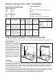
Substitution of the nozzles
- Remove all pan supports, burner caps, rings and
crowns;
- With a tubular spanner no. 7 unscrew and remove
(see diagram) the nozzles substituting them with
those corresponding to the type of gas used (see
Technical data);
- Remount the parts carrying out the operations
described in reverse. Upon completion remove
existing gas type label and stick the relevant gas
type label near the gas supply pipe.
If the pressure of gas used is different (or variable) from
that foreseen an appropriate pressure regulator should
be installed on the entry tube. In case pressure
regulators for U-LPG are used these should conform to
the regulations in force.
Regulation of the minimum
To regulate the minimum:
- bring the tap to the minimum flame position.
- extract the knob.
- in case of conversion from natural gas to U-LPG,
tightly screw the by-pass screw (see diagram);
- when converting from U-LPG to natural gas unscrew
about ½ turn by-pass screw, until a regular small
flame is reached.
Finally check that by quickly turning the tap from
the maximum position to the minimum position the
burner is not extinguished; remount the parts
carrying out the operations described in reverse.
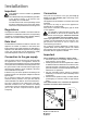
Adaptation to different types of gas
FO 0392
By pass screw
Electrical connections
The appliance is designed to be connected to 230-240
V monophase electricity supply.
The connection must be carried out in compliance with
the laws and regulations in force.
Before the appliance is connected:
1) check that the main fuse and the domestic
installation can support the load (see the rating label);
2) check that the power supply is properly earthed in
compliance with the current rules;
3) check the socket or the double pole switch used for
the electrical connection can be easily reached with
the appliance built in the furniture unit.
The appliance is supplied with a connection cable
provided with a plug, able to support the load marked
on the identification plate. The plug has to be fitted in a
proper socket.
If connecting the appliance directly to the electric
system, it is necessary that you install a double pole
switch between the appliance and the electricity supply,
with a minimum gap of 3 mm. between the switch
contacts and of a type suitable for the required load in
compliance with the current rules.
The connection cable has to be placed in order that, in
each part, it cannot reach a temperature 50 °C higher
than the room temperature.
The brown coloured phase cable (fitted in the terminal
block contact marked with "L") must always be
connected to the network phase.