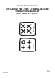
Piani di cottura - Built-in hobs - Ankastre Gazlý Ocak ISTRUZIONI PER L'USO E L'INSTALLAZIONE INSTRUCTION BOOKLET KULLANIM KILAVUZU Mod.
English Important Safety Information These warnings are provided in the interest of safety. You MUST read them carefully before installing or using the appliance. About Installation, Cleaning and Manteinance • It is mandatory that all operations required for the installation are carried out by a qualified or competent person, in accordance with existing rules and regulations. • Disconnect the appliance from the electrical supply, before carrying out any cleaning or manteinance work.
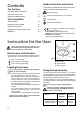
Contents Guide to Use the instructions The following symbols will be found in the text to guide you throughout the Instructions: For the User Important Safety Information 11 Instruction for the User 12 Cleaning and Maintenance 14 For the Installer Technical Data 15 Instruction for the Installer 15 Electrical Connection 16 Adaptation to different types of gas 17 Building In 18 Safety Instructions Step by step instructions for an operation Hints and Tips Environmental information - Thi
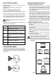
Use of electric plates Using the plate correctly To switch on the plate, turn the relevant knob to the required position. The plates are regulated by a 7 position switch: Position 0: off Position 1: minimum disbursement of heat Position 6: maximum disbursement of heat The pilot light signals the connection of the electric plate. Saucepans and frying pans (Fig.
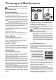
Cleaning and Maintenance Disconnect the appliance from the electrical supply, before carrying out any cleaning or manteinance work. FO 2265 General cleaning Wash the enamelled components with warm soapy water. Never use abrasive cleaners Frequently wash the "caps" and the "crowns" with hot soapy water, carefully taking away any built-up of food. The cap and crown of each burner are secured with two screws.
Technical Data Gas Burners Rating Rapid Burner Auxiliary Burner Semirapid Burner Appliance Class Category 2,9 kW (G20) - 2,7 kW (G30/G31) 1 kW 1,9 kW 3 II 2H3+ EHX 689: Ø 180 mm. 1,8 kW Electric Supply 230 V 50 Hz Hob recess dimensions Setting EGG 676: Electric hotplate Natural gasG 20 / 20 mbar LPG G30/G31 28-30/37 mbar Gas connection Length Width 550 mm. 470 mm.
Electrical Connection The appliance is designed to be connected to 230 V monophase electricity supply. YES The connection must be carried out in compliance with the laws and regulations in force.
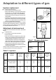
Adaptation to different types of gas Injectors replacement • Remove the pan supports. • Remove the burner's caps and crowns. • With a socket spanner 7 unscrew and remove the injectors (Fig. 7), and replace them with the ones required for the type of gas in use (see table 2). • Reassemble the parts, following the same procedure backwards. • Replace the rating label (placed near the gas supply pipe) with the relevant one for the new type of gas supply.
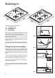
Building In SR SR A P A SR R R 52 0 64 0 52 64 0 0 Dimensions are given in millimeters A SR R P = Auxiliary burner = Semirapid burner = Rapid Burner = Electric plate These hobs can be inserted in a built-in kitchen unit whose depth is between 550 and 600 mm. The hobs dimensions are shown in the relevant diagram. The edge of the cut out must have a minimum distance from the rear wall of 55 mm.
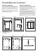
Possibilities for insertion Kitchen unit with door Kitchen unit with oven Proper arrangements must be taken in designing the forniture unit, in order to avoid any contact with the bottom of the hob which can be heated when it is operated. The recommended solution is shown in Fig. 12. The panel fitted under the hob should be easily removable to allow an easy access if a technical assistance intervention is needed. The hob recess dimensions must comply the indication given in Figs.