
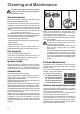
User manual


17
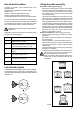
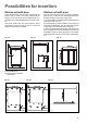
Injectors replacement
• Remove the pan supports.
• Remove the burner's caps and crowns.
• With a socket spanner 7 unscrew and remove the
injectors (Fig. 7), and replace them with the ones
required for the type of gas in use (see table 2).
• Reassemble the parts, following the same procedu-
re backwards.
• Replace the rating label (placed near the gas supply
pipe) with the relevant one for the new type of gas
supply. You can find this label in the package of the
injectors supplied with the appliance.
Should the feeding gas pressure be different or variable
compared with the required pressure, an appropriate
pressure adjuster must be fitted on the gas supply pipe,
in compliance with the rules in force.
Fig. 7
FO 0392
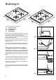
Adjustment of minimum level
To adjust the minimum level of the burners, proceed as
follows:
• Light the burner.
• Turn the knob on the minimum position.
• Remove the knob.
• With a thin screwdriver, adjust the by-pass screw
(see Fig. 8). If changing from natural gas to LPG,
completely tighten clockwise the screw, until a
small regular flame is obtained. If changing from
LPG to natural gas unscrew about 1/4 turn the by-
pass screw, until a small regular flame is obtained.
• Finally check the flame does not go out when
quickly turning the knob from the maximum position
to the minimum position.
This procedure can easily be carried out, anyhow the hob
has been positioned or built in the working top.
Burner Ø By-pass
in 1/100
of mm.
Auxiliary 28
Semi-rapid 32
Rapid 40
Table 1 : By-pass diameters
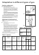
Table 2 : injectors
Adaptation to different types of gas
TYPE TYPE OF INJECTORS NOMINAL REDUCED NOMINAL NOMINAL
OF GAS BURNER MARKS POWER POWER POWER PRESSURE
1/100 mm INPUT k W mbar
KW m
3
/h g/h
Rapid (large) 119 2,9 0,65 0,276 -
Semi-rapid (medium) 96 1,9 0,45 0,181 - 20
Auxiliary (small) 70 1,0 0,33 0,095 -
Rapid (large) 86 2,7 0,65 - 195
Semi-rapid (medium) 71 1,9 0,45 - 137 28-30/37
Auxiliary (small) 50 1,0 0,33 - 72
NATURAL
GAS
G 20
LPG
(Buthane/
Propane)
Fig. 8