
Manual

Blower Motor Systems Installation
previously removed. If it is removed, reattach the
motor electrical plug to the connector on the
blower motor assembly.
Complete Preparation
1. Determine and make all necessary cuts for the
vent system.
IMPORTANT: When cutting or drilling into the ceiling
or wall, do not damage electrical wiring or other hid-
den utilities.
2. Determine the location where the 1/2"(1.3 cm)
wiring conduit will be routed through the ceiling or
wall between the remote blower and the hood insert.
3• Drill a 1W' (3.2 cm) hole at this location.
4. Locate the electrical terminal boxes in the remote
blower housing and hood insert (see "Complete
Preparation" in the "Prepare Location" section).
Remove the terminal box covers and set the
covers and screws aside.
joints. Use furnace duct tape to seal all joints
tightly.
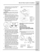
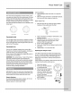
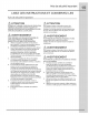
A. Vent System
B. Remote Blower Motor
C. Ceiling
D. Roof rafters / Plywood
E. Remote Blower Wiring
Conduit
i E Hood Insert Wiring
Conduit
G. Hood Insert
Make Electrical Connections for Remote Blower
• ' _ Motor System
° WARNING
Electrical Shock Hazard
Disconnect power before servicing.
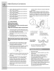
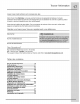
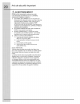
A. Electrical terminal box Replace all parts and panels before operating.
B. Electrical knockout Failure to do so can result in death or electrical
5. Remove the electrical knockout from the remote shock.
blower housing and hood insert (see "Preparation"
in the "Prepare Location" section) to prepare for Electrical Connection Inside Remote Blower System
the installation of the UL listed or CSA approved 1. Disconnect power•
1 " ........
V2 (1.3 cm) wmng conduit and conduit connector. 2. Connect the wires from the wmng conduit to the
NOTE: Strain relief conduit are supplied with wires from the motor electrical plug cable inside
remote blower hardware. ,, the remote blower housing terminal box.
6. With the hood insert mounted (see the InstallHood
" ' 1 " '' ' _ '_._,.._
Insert section), run the V2 (1 3 cm) wlnn conduit
. g
between the remote blower motor housing and the _ _ _F'Xk C D
hood insert. Pull enough 1/2"(1•3 cm) wiring conduit i{_ ,X-_L ii / E...........__ ..................................
/ .................o, j
to allow for easy connection to the terminal boxes , /_:\"_ I /_ F ,P_ y_(/_2//2//_'_
G / \ _\lli
n the remote bower hobs ng and hood nsert \_ _ _ I _G ......................................................,_//f_;__i_/_7!'_'_\il....................H
7. Run the six 18 AWG wires through the 1/_ (1.3 /L._._[I/_
cm) w r ng condu t and condu t connectors and _ :_" __:::.._ A
into the terminal boxes on the remote blower __i_i_((2P-,
housing and hood insert. Leave enough wire length __, __
ineach terminal box to make the wiring connections.
8. Install the conduit connectors and conduit to the
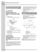
remote blower housing and hood insert electrical A.UL listed or CSA approved E. Red wires
terminal boxes. _" (1.3 cm)wiring conduit E Blue wires
N TE" tr in r li f n it r li with BUL stedwreconnectors G Graywres
O .S a ee co du aesupped • . • , , , .
..... C.BlacK wires H. Green [or yellow/green) ana
remote plower naraware. U.White wires green/yellow wires
9. Connect the vent system to the hood insert and I.Motorelectricalplugcable
remote blower motor system. Use clamps at all