
Service manual


EElleeccttrroonniicc CCoonnttrrooll
3-22
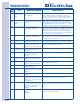
EErrrroorr
CCooddee
E72
E73
E74
E91
E92
E93
E94
E97
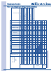
EA1
EA2
EA3
EA4
EA5
EF1
EF3
EF8
FFaauulltt
Outlet Control
Thermistor short
circuit
Inlet Control
Thermistor open
circuit.
Motor Relay failure
Communication
Error
Incompatible
protocol
Machine configura-
tion checksum
error
Cycle configuration
checksum error.
Program mismatch
Main Supply
Frequency out of
Range
Voltage too high
Voltage too low
Improper home
wiring
Main V Sensing
failure
Vent Blocked
Max Timeout Timer
Key Stuck
PPoossssiibbllee FFaauulltt CCoonnddiittiioonnss
Outlet Control Thermistor or
wiring defective.
Inlet Control Thermistor or wiring
defective.
Motor Relay stuck open or
closed; Wiring defective.
Wiring, Electronic Control Board,
or Interface Board defective
Electronic Control Board incom-
patible with Interface Board
Wrong configuration data loaded,
Interface Board or Electronic
Control Board or wiring defective.
Wrong configuration data loaded
or Electronic Control Board
defective
Wrong configuration data loaded,
Electronic Control Board
defective
Line frequency out of limits or
Electronic Control Board faulty.
Line voltage too high or
Electronic Control Board faulty.
Line voltage too low or Electronic
Control Board faulty.
Line connections in home faulty,
wiring or Electronic Control Board
defective.
Electronic Control Board
defective
High vent restriction, Exhaust
Control Thermistor, Inlet Control
Thermistor, or Electronic Control
Board defective.
Exhaust blocked; Exhaust
Control Thermistor, Inlet Control
Thermistor, Contact Sensor or
Electronic Control Board
defective.
Console button or Interface
Board
defective
PPoossssiibbllee SSoolluuttiioonnss
Check resistance of Outlet Control Thermistor, and check
wiring for short circuit across Thermistor connections.
Resistance should be between 4.9K Ohm and 6.2K Ohm at
room temperature (68-77° F or 20-25° C). Replace Outlet
Control Thermistor and/or wiring and retest.
Check resistance of Inlet Control Thermistor, and check
wiring for open circuit. Resistance should be between 47K
Ohm and 66K Ohm at room temperature (68-77° F or 20-25°
C). Replace Inlet Control Thermistor and/or wiring and retest.
If motor runs continuously with power applied check for short
circuit across motor relay (RL2), or L1 applied to motor relay
output (J3-1) with cycle stopped. If motor does not start
when “start” key is pressed, check for open circuit between
L1 and motor relay connection (J3-2). If no wiring problems
found, replace Electronic Control Board.
Check connections between Electronic Control Board and
Interface Board. If no wiring problems, replace Electronic
Control Board or Interface Board.
Check if correct Interface Board console and Electronic
Control Board are installed. Replace appropriate hardware.
Check if correct Interface Board and console are installed.
Replace Interface Board and/or console.
Replace Electronic Control Board.
Replace Electronic Control Board.
Check frequency of line voltage.
Check amplitude of line voltage.
Check amplitude of line voltage.
Check wiring at terminal block for L1-N-L2 wired incorrectly.
Replace Electronic Control Board.
Check vent restrictions and resistance values of Exhaust
Control Thermistor and Inlet Control Thermistor.
Check vent restriction, Contact Sensor, and resistance values
of Exhaust Control Thermistor and Inlet Control Thermistor.
Check buttons for activation when pressed. Replace console
or Interface Board as appropriate