
Service manual


4-7
CCoommppoonneenntt TTeeaarrddoowwnn
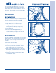
TToopp PPaanneell RReemmoovvaall
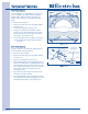
The top panel is secured with a metal tab at each
front corner and two screws at the rear of the unit.
To remove the top panel:
1. Pull unit from its installation position to access
the rear of the unit.
2. Using a #2 square bit screwdriver, extract
the two screws securing the top panel to the
unit frame. (See Figure 4-15)
3. From the front of the unit, push the top panel
towards the rear until free of the metal tabs,
then lift top panel off of unit.
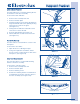
CCoonnssoollee aanndd UUsseerr IInntteerrffaaccee RReemmoovvaall
The console is secured with a screw on each
corner that passes through a bracket mounted to
the console and fastens into the unit frame. The
wire harness connects to the right hand side of the
user interface mounted inside the console.
To remove the console:
1. Remove the top panel.
2. Using a #2 square bit screwdriver, extract
the screw from each side securing the console
mounting bracket to the top of the unit frame.
(See Figure 4-16)
3. Carefully lift console off the front panel, using
care not to strain wire harness connections.
4. Carefully position the console to access the
electrical connection and disconnect the wire
leads from the user interface.
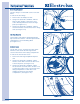
5. Using a #2 square bit screwdriver, extract
the six screws securing the control assembly
to the console panel. Carefully lift the control
assembly from the console panel.
(See Figure 4-17)
6. Separate the button carrier from the control
assembly by releasing the two retaining
latches on the end with the Start /Pause
button. Lift slightly and pull tab out of the slot
closest to the cycle selector knob.
7. Separate the cycle control knob housing from
the control assembly by releasing the three
retaining latches on the outer edge of the
control assembly. Carefully lift up housing until
control knob is free of shaft, then lift housing
off of the control assembly.
FFiigguurree 44--1155..
FFiigguurree 44--1177..
FFiigguurree 44--1166..
Retaining
Tab
Screws
Electrical Connection
Screw
Screw
Screws
NNOOTTEE::
When removing the control board, release
the circuit board at the base of the cycle control
knob first by pushing back the retaining latches
and lifting the circuit board out from under the
latches. Then continue with the removal of the
main circuit board.
8. The control board and display is removed by
pushing back the retaining latches securing
the control board to the control assembly, then
lifting it out of the control assembly.