
Service manual

4-9
CCoommppoonneenntt TTeeaarrddoowwnn
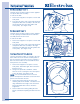
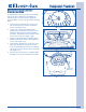
CCoonnttrrooll AAsssseemmbbllyy
The control assembly is mounted to a bracket
along the top right hand side of the unit frame.
The wire harness connects to multiple positions on
the circuit board and must be disconnected before
removing from the unit.
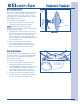
To remove the control assembly:
1. Remove the top panel.
2. Using a #2 square bit screwdriver, extract
the two screws securing the control assembly
to the mounting bracket. (See Figure 4-20)
3. Carefully handle the control assembly while
disconnecting the electrical leads from the
control assembly.
4. Release the retaining latches securing the
control assembly cover to the control housing.
Lift cover from housing.
5. The circuit board is secured on one end of the
housing with retainers. Lift from opposite end
and pull out from under retainers to remove
the circuit board.
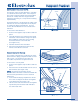
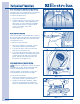
CCoonnttrrooll BBooxx BBrraacckkeett RReemmoovvaall
The control box bracket is secured by two
retaining tabs and two screws at the front and rear
inner panels.
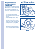
To remove the control box bracket:
1. Remove the top panel, rear panel, console and
front panel.
2. If replacing the bracket, remove the control
box. If removing the bracket to access the
drum or heating components, it is not
necessary to remove the control box.
3. From both ends of the bracket, use a #2
square bit screwdriver and extract the four
screws securing the bracket to the inner front
and rear panels. (See Figure 4-21)
4. Lift upwards to release the tabs, then pull out
of the unit. If control box is still mounted to
bracket, swing bracket over rear inner panel.
FFiigguurree 44--2200..
NNOOTTEE::
The gas dryer uses the same housing for
the control board, but will have one less electrical
connection.
Screw
Retaining Latches
Screw
Electrical
Connection
FFiigguurree 44--2211..
Screws
Front
Inner
Panel
Tabs