
Service manual

4-11
CCoommppoonneenntt TTeeaarrddoowwnn
IInnlleett TThheerrmmiissttoorr RReemmoovvaall ((IInnlleett NNTTCC))
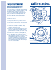
The function of the rear inlet thermistor / Inlet NTC
is to determine the heater status. If the tempera-
ture reads over the threshold, the heater(s) will be
turned off. A faulty inlet NTC may prevent the
heater(s) from turning on, or may turn the heater(s)
off prematurely.
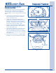
The inlet thermistor is inserted into the outlet of the
heat duct to sense the temperature of the air prior
to entering the drying compartment. A screw
secures the inlet thermistor to the outside of the
heat duct.
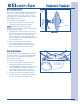
To remove the inlet thermistor:
1. Remove the top panel, top rear brace and rear
panel.
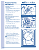
2. The inlet thermistor is mounted to the top left
hand side of the heat duct. Using a #2 square
bit screwdriver, extract the screw securing
the inlet thermistor to the heat duct.
(See Figure 4-25)
3. Pull inlet thermistor from heat duct.
4. Disconnect inlet thermistor from from wire
harness at the Molex connector.
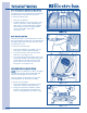
MMooiissttuurree SSeennssiinngg BBaarr RReemmoovvaall
The moisture sensing bar is mounted to the lower
back wall of the drying compartment and secured
with a screw. The electrical connections are
accessible only with the rear panel removed.
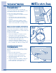
To remove the console panel:
1. Remove the top panel, top rear brace and rear
panel.
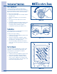
2. Disconnect the electrical leads from the sensor
bar terminals. (See Figure 4-26)
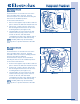
NNOOTTEE::
The electrical connection can be
disconnected at the molex connector and with the
removal of the ground wire screw as shown in
Figure 4-27.
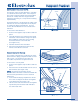
3. From inside the drying compartment, extract
the screw securing the moisture sensing bars
to the back wall. (See Figure 4-27)
4. Lift the screw end of the moisture sensing bars
up and away from the back wall until tab is
free of the back wall.
FFiigguurree 44--2266..
FFiigguurree 44--2277..
Screw
Ground
Wire
Tab
Heat
Duct
FFiigguurree 44--2255..
Screw
Electrical Connection
Electrical Connection