
Service manual


4-19
CCoommppoonneenntt TTeeaarrddoowwnn
EElleeccttrriicc HHeeaatteerr FFuunnccttiioonn
The electric heater assembly consists of three
5500 Watt elements, that are energized as needed
by the electronic control.
Under normal circumstances where the unit is
starting at ambient temperature (below 100°F), all
heating elements should turn on. Above 100°F (in
the exhaust), any number of heating elements may
be on depending on selected cycle, temperature
settings, options and previous state of elements.
Unless there is a high vent restriction or faulty
thermistor, the heater element conditions will be
controlled by the exhaust NTC.
HHeeaatteerr AAsssseemmbbllyy RReemmoovvaall ((EElleeccttrriicc MMooddeellss))
NNOOTTEE::
If unit was used prior to service, the heater
assembly may be hot. Refer to Warnings and
Cautions at the beginning of this section.
The heater assembly is secured to a mounting
bracket in the front and secured with two screws.
The rear of the heater slides into the heat duct and
is secured with a screw to the right rear of the
heater assembly.
1. Remove the top panel, rear panel, console,
front panel, front inner panel, drum and
heat shield.
2. Disconnect all wire leads from the components
mounted to the heater assembly, labeling as
needed to assure proper connection.
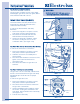
3. Using a #2 square bit screwdriver, extract
the two screws at the front of the heater
assembly and the single screw at the right rear.
(See Figure 4-47)
4. Pull the heater assembly from heat duct.
TThheerrmmaall LLiimmiitteerr aanndd SSaaffeettyy TThheerrmmoossttaatt RReemmoovvaall
((EElleeccttrriicc MMooddeellss))
The thermal limiter and safety thermostat are
mounted to the left side of the heater assembly
and secured in position with screws.
To remove the thermal limiter and safety
thermostat:
1. Remove the top panel, rear panel, console,
front panel, front inner panel and drum.
2. Disconnect the electrical leads from the
thermistor that is to be checked or replaced.
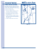
3. Using a #2 square bit screwdriver, extract
the two screws securing the thermistor
mounting bracket to the heater assembly.
(See Figure 4-48)
FFiigguurree 44--4477..
Screw
Electrical
Connections
Screws
FFiigguurree 44--4488..
Thermal
Limiter
Safety
Thermostat