
Service manual


4-21
CCoommppoonneenntt TTeeaarrddoowwnn
MMaanniiffoolldd aanndd BBuurrnneerr AAsssseemmbbllyy BBrreeaakkddoowwnn
((GGaass MMooddeellss))
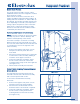
In order to separate the manifold from the valve
body, the burner assembly must be removed from
the valve body. A screw at the rear of the unit
secures the manifold to the rear frame as well as
two screws securing the manifold to the unit base.
All electrical connections should be disconnected
prior to removing the manifold.
To remove the manifold and burner assembly:
1. Remove the top panel, console and front
panel.
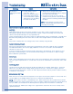
2. Disconnect all electrical connections from gas
valve, coils, ignitor and wire harness.
(See Figure 4-52)
3. Using a #2 square bit screwdriver, extract
the screw from the rear of the unit base
securing the manifold mount to the unit base.
(See Figure 4-52)
4. Extract the two screws from the manifold
mount located beneath the combustion tube.
(See Figure 4-52)
5. Extract the screw from the bent down tab at
the entrance of the combustion tube.
(See Figure 4-52)
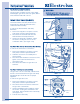
6. The gas valve and burner assembly with the
manifold attached, can now be pulled out of
the combustion tube.
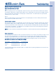
7. Using a #2 square bit screwdriver, extract
the screws securing the burner assembly to
the gas valve mounting bracket.
(See Figure 4-53)
8. Extract the four screws securing the gas valve
mounting bracket to the gas valve and
manifold. Remove the gas valve mounting
bracket from the assembly. (See Figure 4-52)
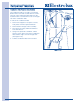
9. Extract the screw securing the ignitor to the
gas valve mounting bracket. Lift the ignitor off
the tab and remove from bracket.
(See Figure 4-53)
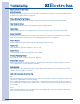
10. Separate the manifold from the gas valve by
using a 1-3/16” open end wrench or a large
adjustable wrench, and grabbing the gas valve
body on the square section directly above the
manifold. Turn gas valve body counter
clockwise to remove. (See Figure 4-54z)
FFiigguurree 44--5522..
FFiigguurree 44--5533..
Screw
Ignitor Screw
Screws
Screws
Valve Mounting
Bracket Screws
FFiigguurree 44--5544..
Manifold