
User manual

the top behind the hood), the cooker must
not be pushed in under a tiled edge or similar.
There must be a clear surface of at least 40
cm on both sides of the cooker.
Make sure that the cooker cable does not get
crushed when moving the cooker.
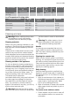
Adjusting the height of the base
If you wish to adjust the height, please read
the following points before you start.
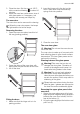
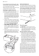
1. Lay down the cooker gently (See illustra-
tion). Use, for example, the polystyrene
from the packaging between the cooker
and the floor as protection. Remember to
locate a protective layer under the lower
rear corners of the cooker sides to pro-
tect the floor.
2. Unscrew the screws A (4 screws, see il-
lustration). Pull out the inner base slightly
if you only wish to change the height. Pull
the brackets on which the wheels and
feet are fitted. Be careful, there are
sharp edges under the cooker.
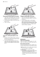
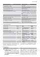
3. Screw in the screws again A in one of the
holes for a bench height of 850 to 920
mm. The distance between the holes var-
ies between 7 mm and 14 mm (see illus-
tration A).
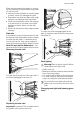
4. Lift the cooker upright and connect it up
to the mains. Push the cooker back into
position and make sure that it is abso-
lutely level before fitting the safety equip-
ment.
A
A
A
A
A
14
920
850
7
7
14
14
14
Horizontal adjustment
The cooker must be level so that, for exam-
ple, fat spreads evenly in the frying pan. Place
a spirit level or a frying pan containing water
on the ceramic glass plate when you want to
check whether the cooker is level. If neces-
sary, from the front of the plinth, you can ad-
just the cooker wheels and feet by 15 mm.
Use a screwdriver to adjust the rear wheels
and a Polygrip for the front feet.
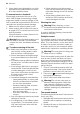
The anti-tip guard
Warning! The anti-tip guard must be
fitted to prevent the cooker from tipping
over with abnormal loads. The anti-tip
guard only works when the cooker has
been pushed into place.
How you install the ant-tip guard:
1. Before fitting the anti-tip guard, make
sure that the cooker has been adjusted
to the correct height and is standing level.
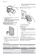
2. The attachment (B) is fitted to the left side
when delivered. Measure out where the
anti-tip guard (A) is to be located, 60 mm
down from the edge of the hob and 50
mm from the wall (cupboard). Screw it
firmly into solid material or use suitable
reinforcement. The entire anti-tip guard (A
+B) can also be located on the right-hand
side (See fig. 1).
Make sure that the surface behind the cooker
is smooth. If there are tiles or a moulding be-
hind the edge of the ceramic glass plate then
there must be a space with the same dimen-
sion between the anti-tip guard and the wall.
This is so that the anti-tip guard is firmly at-
tached to the cooker and functions correctly.
Check that the anti-tip guard projects at least
20 mm into the hole in the back of the cooker
(B) when the cooker is pushed in (See fig. 2).
30 electrolux