ESV09CRS-B2 ESV12CRS-B2 ESV09CRR-C6 ESV09CRR-C7 EN AIR CONDITIONER ESM09CRR-B3 ESM12CRR-B3 ESM18CRR-B3 INSTALLATION MANUAL 2
www.electrolux.com CONTENTS 1. SAFETY INSTRUCTIONS..................................................................................... 3 2. BEFORE INSTALLATION...................................................................................... 5 3. PRODUCT INSTALLATION................................................................................... 8 4. TEST AND RUNNING......................................................................................... 19 5. APPENDIX...........................
ENGLISH 1. 3 SAFETY INSTRUCTIONS Before the installation and use of the appliance, carefully read the supplied instructions. The manufacturer is not responsible if an incorrect installation and use causes injuries and damages. Always keep the instructions with the appliance for future reference. 1.1 Children and vulnerable people safety WARNING! Risk of suffocation, injury or permanent disability.
www.electrolux.com • For safety, be sure to turn off the circuit breaker before performing any maintenance or cleaning or when the product is not used for an extended period of time. Accumulated dust may cause fire or electric shock. • Select the most appropriate temperature. It can save electricity. • Do not keep windows and doors open for a long time during operation. It will result in insufficient performance. • Do not block the air inlet or outlet.
ENGLISH 2. BEFORE INSTALLATION 2.1 Tools needs for installation 1. 2. 3. 4. 5. 6. 7. 8. 9. Level gauge Screw driver Electric drill Hole core drill Flaring tool set Specied torque wrenches Spanner (half union) A glass of water Hexagonal wrench 10. 11. 12. 13. 14. 15. 16. 17. Gas-leak detector Vacuum pump Gauge manifold Pipe expander Multimeter Pipe cutter Measuring tape Other tools 2.
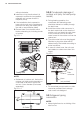
6 www.electrolux.com www.electrolux.com 2.3 Product Description Space to the ceiling 3 2 ≥15cm 1 Space to the wall ≥15cm Space to the wall ≥15cm ≥3m 7 8 9 10 Air outlet side 4 5 20 6 ≥50cm Space to obstruction 13 15 16 17 Air inlet side Space to the wall ≥3 0c m 14 ≥30cm ≥50cm m ≥2 Space to the wall 11 Air outlet side 18 19 12 NOTE All the pictures in this manual are for explanation purposes only.
ENGLISH 2.4 Installation site • Do not install the unit in areas with: –– strong heat sources; –– vapours or flammable gases; –– contamination with oil particles; –– high frequency electromagnetic equipment (e.g. welding equipment or medical devices); –– high salinity (e.g. close to coastal areas); –– sulphuric gas (e.g hot water springs); –– poor air quality. Indoor unit • Maintain the minimum installation distances specified in this document. Do not block the air inlet or the air outlet.
www.electrolux.com 3. PRODUCT INSTALLATION 3.1 Indoor unit installation 3.1.3 Connective pipe 3.1.1 Installing the Wall Mounting Plate 1. For the left-hand and right-hand piping, remove the pipe cover from the side panel. The pipe cover can be kept as it may be used when relocating the air conditioner to any other place. 2. For the rear-right-hand and rear-lefthand piping, install the piping as shown in Fig.3.1.3-1. Bend the connective pipe to be laid at a height of 43mm or less from the wall.
ENGLISH 2. When connecting extension drain hose, insulate the connecting part of extension drain hose with a shield pipe, do not let the drain hose slack. 3.1.5 Fastening the Indoor Unit 1. Pass the piping through the hole in the wall. 2. Put the upper claw at the back of the indoor unit on the upper hook of the wall mounting plate, move the indoor unit from side to side to see that it is securely hooked. Fig.3.1.5-1 9 3.1.6 Piping and wrapping 1.
www.electrolux.com without obstacles. 3. Install the unit at the site where it is exposed to as little wind as possible, especially not in areas where it is frequently windy. 4. If the installation site is exposed to heavy winds, such as in coastal areas, place the unit along the widest part of the wall or use protective plates. 5. Be sure there is no obstacle which blocks exhausting air, including shrubs or bushes. Fig.3.2.1-1 3.2.2 Condensate drainage of outdoor unit (only for heat pump model) 1.
ENGLISH 3.3.1 Flaring work Main cause for refrigerant leakage is due to defect in the flaring work. Carry out correct flaring work using the following procedure: 1. Cut the pipes and the cable. • Use the piping kit accessory or pipes purchased locally. • Measure the distance between the indoor and the outdoor unit. • Cut the pipes a little longer than the measured distance. • Cut the cable 1.5m longer than the pipe length. Fig.3.3.1-1 3.
www.electrolux.com 3.4 Piping Connection Fig.3.4.1-3 Cable Ties 3.4.1 Indoor Unit 1. Connecting the indoor unit tubing to the connection piping: • Align the centers of the pipes and sufficiently tighten the flare nut with your hands first. Fig.3.4.1-1 Indoor unit tubing Insulation Material • Ensure to isolate separately the suction pipe from the liquid pipe. Fig.3.4.1-4 Heat Insulation Flare nut Pipes Suction line pipe Liquid line pipe Torque wrench Spanner Fig.3.4.
ENGLISH 3. Hang the indoor unit: 13 Fig.3.4.2-1 • Remove the spacer. • Hook the indoor unit onto the upper portion of the mounting plate (Engage the hooks of the mounting plate into the openings at the rear top of the indoor unit). • Ensure that the hooks are properly seated on the mounting plate by moving the indoor unit in all directions. Fig.3.4.1-8 Upper hook Mounting plate 2. Then, tighten the flare nut with torque wrench until the wrench clicks. Fig.3.4.
www.electrolux.com • Wrap the piping, drain hose and connecting cable from the down to up. • Secure the wrapped piping along the exterior wall using saddle or equivalent. Fig.3.4.3-1 Seal small openings around piping with a gum type sealer 3.4.4 Checking the Drainage 1. Open and lift the indoor unit front panel. • Hold the lower part of the left and right sides of the panel, pull it against you and lift it stops with support. Fig.3.4.
ENGLISH Fig.3.4.4-3 Downward slope • Do not place drain piping as indicated below: Fig.3.4.4-4 Do not rise Accumulated drain water Air Water leakage Water leakage Tip of drain hose dipped in water Water leakage Space less than 50mm Ditch 3.5 Electrical Installation 3.5.1 Safety Precautions Electrical safety rules before starting the installation: 1.
www.electrolux.com 2. Route the power connection cable and signal control wire (for heat pump model only) from back of the indoor unit and pull it toward the front through the wiring hole for connection. 3. Pass the wires through the hole of the Magnetic ring(If supplied). 4. Connect and screw the wires onto the terminal block as identified by their colors. 5. Wrap wires that are not connected with insulating tape so that they do not touch any electrical or metal parts. 6.
ENGLISH 17 3.6 Air Purging and Leakage Test Fig.3.5.3-2 Magnetic ring (If supplied and packed with the accessories) NOTE: • The wiring diagram as shown just for reference only, please refer to the label stickerd on the unit for correct connection. After confirming the above conditions, prepare the wiring as follows: • The screws which fasten the wiring to the terminal block may come loose from vibrations during transportation. • Check and make sure all screws are well fixed.
www.electrolux.com Fig.3.6.1 Outdoor unit Outdoor unit Oil trap (A) (A) (B) (B) Indoor unit Indoor unit Piping length under 4m Piping length 4m or more (A): Maximum Piping Length (B): Maximum Piping Height needed when outdoor unit installed at a lower place than indoor unit). 5. Refer to Appendix(3) for correlative specs about the Pipe length and additional refrigerant amount for split type air conditioner. 3.6.
ENGLISH NOTE: • The schrader valve is inside the charging port. 2. Connect the other charge hose of manifold valve to the vacuum pump. 3. Fully open the Low Side handle of the manifold valve. 4. Operate the vacuum pump to evacuate. After starting evacuation, slightly loose the flare nut of the Low Side valve on the gas pipe side and check if the air is entering (Operation noise of the vacuum pump changes and a compound meter indicates 0 instead of minus), then tighten the flare nut.
www.electrolux.com 4.2 Electrical Safety Check 4.4 Pump Down Perform the electric safety check after completing installation: 1. Earthing work • After finishing earthing work, measure the earthing resistance by visual detection and earthing resistance tester. 2. Electrical leakage check (performing during test running) • During test operation after finishing installation,the service person can use the electric probe and multimeter to perform the electrical leakage check.
ENGLISH 5. APPENDIX Appendix(1) Outdoor Unit Dimension (mm) Indoor Unit Dimension (mm) Mounting Plate Type 660*500*240 750*285*200 A 665*420*280 750*285*200 A 730*545*285 750*285*200 A 800*545*315 750*285*200 A 730*545*285 837*296*205 A 800*545*315 837*296*205 A 800*545*315 952*310*227 B 825*655*310 952*310*227 B 900*700*350 1082*330*233 C 533.7mm 390mm 270.
www.electrolux.com Appendix(2) Minimum Cross-Sectional Area of Power and Power Cables Rated Current of Appliance (A) Nominal Cross-Sectional Area (mm²) >3 and ≤ 6 0.75 >6 and ≤ 10 1 >10 and ≤ 16 1.5 >16 and ≤ 25 2.5 >25 and ≤ 32 4 >32 and ≤ 40 6 Cable Types: Indoor power cable: H05VV-F (if applicable) Power cable: H07RN-F or H05RN-F The size of the power supply cable, signal cable, fuse, and switch needed is determined by the maximum current of the unit.
ENGLISH 23 Appendix(3) Models ESV09CRS-B2 ESV12CRS-B2 ESV09CRR-C6 ESV09CRR-C7 Gas Pipe Liquid Pipe Standard Diameter (mm) Diameter (mm) Length (m) Ø9.52 (3/8") Ø6.35 (1/4") 5 Maximum Length (m) (A) 15 Maximum Additional Height (m) Refrigerant (B) (g/m) 10 12 The Minimum length pipe is 3m Additional refrigerant required for pipe length greater than standard 7.5m installation can be calculated using the following equation: M = (F – 7.
www.electrolux.