
Service manual

Notice
Date Page
01201090
INSTRUCTION
HANDBOOK
0499 4
16
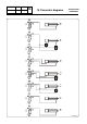
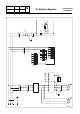
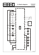
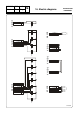
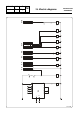
16. Electric diagrams
CONTROL CIRCUIT
AUTOMATE CONNECTION
Diagram no 31100256
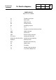
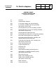
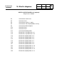
A1 Converter
A2 Programmable automate
BP1 Push-button, loading side cage positioning
BP2 Push-button, unloading side cage positioning
(with barrier machine only)
DP1 Proximity detector, presence of loading side door
DP2 Proximity detector, presence of unloading side door
(with barrier machine only)
DP3 Proximity detector, indexing of cage
DP4 Proximity detector, door jack in rear position (optional)
EV1 Drum door unlocking pilot valve, loading side
EV2 Drum door unlocking pilot valve, unloading side
(optional with barrier machine only)
EV3 Cage door unlocking pilot valve, unloading side
(with barrier machine only)
EV4 Cage unlocking pilot valve
EV5 Cage locking pilot valve
FC1 Unlocking cage
FC2 Locking cage
KA3 Authorization of loading side door opening
KA4 Authorization of unloading side door opening
(with barrier machine only)
KA7 End of washing cycle
KA8 Diode control, loading possible
KA9 Diode control, unloading possible
(with barrier machine only)
KM1 Motor contacteur
KM2 Safety contact relay