
User manual


GB
17
Oven lamp
The oven lamp is controlled by a switch placed in the facia-
panel of the models supplied.
Spit
Spit is controlled by a switch placed in the facia-panel of
the models supplied.
Warning pilot lights
Red pilot light. When it is switched on it indicates that a
heating element is on.
Orange pilot light. When it is switched on it indicates that
the oven thermostat is on.
CLEANING
General information and precautionary measures
Always disconnect appliance from the electricity
supply before you start cleaning.
Close the gas feed cock.
Never throw water directly on still warm components.
CRYSTAL SURFACES
To clean crystal surfaces (cooker top and oven door) use a
sponge with a small quantity of liquid detergent, then with
a sponge soaked with warm water and at the end with a
dry cloth.
GLAZED, PAINTED AND STAINLESS
STEEL SURFACES
Clean the range glazed and painted parts in the same way
as per crystal surfaces (see above). Clean when elements
are cold, only.
Use neither metallic and/or plastic, sponges nor abra-
sive powders nor corrosive sprays.
Neither sprinkle nor wash the resistances and the ther-
mostat bulb with acid-based products.
The manufacturer declines all responsibility for any
damages caused to persons, animals and things
should the appliance not be cleaned properly.
MAINTENANCE
General information and precautionary measures
Always disconnect appliance from electricity supply
before you start maintenance operations and make su-
re that the gas feed cock is closed.
Rubber gas feed pipe replacement
We suggest you to check the rubber gas feed pipe state of
preservation every now and then and to replace it every fi-
ve years.
Should it present any fissure, cut, abrasion or burning re-
place it immediately with a new pipe in compliance with
provisions in force.
Feed cable replacement
We suggest you to check the feed cable state of preserva-
tion every now and then.
Should it present any fissure, cut, abrasion or burning re-
place it immediately with a new cable corresponding to the
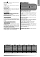
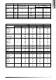
“Feed cables types and sections” table.
To replace cable you should proceed as follows:
- Disconnect appliance from the electricity supply
- Open the terminal strip cover.
- Remove the three screws fixing the cable terminals and
the screw fixing the cable press.
- Connect the new feed cable to the cooker terminal strip
keeping the ground wire length longer than that of the
phase and neutral wires.
- Close the terminal strip cover.
N.B. Mind that at no point the feed cable should reach
a temperature higher than 75K.
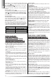
Electric ovens power
Convention oven 2,00 kW
Forced convention oven 1,80 kW
Grill 2,10 kW
Voltage 230 V~
FEED CABLES TYPES TYPE OF INPUT INPUT INPUT INPUT
AND SECTION CABLE 230 V~ 230 V~ 3 400 V~ 2N 400 V~ 3N
TOTAL GAS H05 RR-F 3x0,75 mm
2
///
MIXED UP TO 1000 W H05 RR-F 3x0,75 mm
2
///
MIXED UP TO 200 W H05 RR-F 3x1 mm
2
///
MIXED UP TO 3400 W H05 RR-F 3x1,5 mm
2
4x1,5 mm
2
4x1,5 mm
2
5x1,5 mm
2
MIXED UP TO 3900 W H05 RR-F 3x2,5 mm
2
4x2,5 mm
2
4x2,5 mm
2
5x1,5 mm
2
* ELETTRIC UP TO 8400 W H05 RR-F 3x2,5 mm
2
4x2,5 mm
2
4x2,5 mm
2
5x1,5 mm
2
* ELETTRIC UP TO 9400 W H05 RR-F 3x4 mm
2
4x2,5 mm
2
4x2,5 mm
2
5x2,5mm
2
* The contemporaneity factor was taken into account