EXM18HV1W EXM24HV1W EN SPLIT TYPE ROOM AIR CONDITIONER it Condizionatore split per ambienti es Acondicionador de aire tipo split TR SPLIT TIPI ODA KLIMASI INSTALLATION MANUAL 2 Manuale per l’installazione manual de instalación 24 MONTAJ KILAVUZU 68 46
Congratulations Table of Contents Congratulations and thank you for choosing a splittype air conditioner. We are sure you will find your new air conditioner a pleasure to use. Congratulations .......................................... 2 Before you use the air conditioner, we recommend that you read through the entire user manual, which provides the description of the air conditioner and its functions. Notice for Installation .................................
Safety precautions Please ready this installation manual and the user manual before installation and carefully store in a handy place for later reference. Inside this manual you will find many helpful hints on how to use and maintain your air conditioner properly. Electrical work must be installed by a licensed electrician. Be sure to use the correct rating of the power plug and main circuit for the model to be installed.
Before Installation Tools Needs for Installation 1 2 3 4 5 6 7 8 9 Level gauge Screw driver Electric drill Hole core drill ( 55mm / 70mm) Flaring tool set Specified torque wrenches Spanner (half union) A glass of water Hexagonal wrench (4mm) 10 11 12 13 14 15 16 17 Gas-leak detector Vacuum pump Gauge manifold Users manual Thermometer Multimeter Pipe cutter Measuring tape Items required for installation (Per indoor and outdoor unit) Number Name of Accessories Indoor unit mounting plate Clip anchor Self-
Space to the ceiling 15cm above Product Description Indoor Unit Space to the wall 15cm above Space to the wall 3m a bove 2.
7 Select place about 1m or more away from a TV set or any other electric appliance. Installation Site Instruction A proper installation site is vital for correct and efficient operation of the unit. Avoid the following sites where: • strong heat sources, vapour, flammable gas or volatile liquids are emitted. • high-frequency electro-magnetic waves are generated by radio equipment, welders or medical equipment. • salt-laden air prevails (such as close to coastal areas).
Rooftop Installation 1 If the outdoor unit is installed on a roof structure, be sure to level the unit. 2 Ensure the roof structure and anchoring method are adequate for the unit location. 3 If the outdoor unit is installed on roof structures or external walls, this may result in excessive noise and vibration, and may also be classed as non-serviceable installation.
Outdoor Unit Installation Step 1: Securing of Outdoor Unit • Anchor the outdoor unit by fixing the 4 holes existent in its based with 4 bolts and nuts of 10 mm tightly (not included). Place the outdoor unit over a horizontal concrete or rigid surface (never directly over grass or land). Air inlet Air inlet Step 2: O utdoor Condensate Drainage (only for heat pump model) • During heating operation, the condensate and defrosting water should be drained out reliably through the drain hose.
Mounting Plate Type A Mark on on the the middle middle of of itit Mark Left Left 55mm 55mm 45 (Rear piping piping hole) hole) 45 (Rear 150 150 605 605 317 317 Space Space to the the to wall wall 150mm 150mm above above Wall 45 45 45 45 Wall Space 35 35 Space to the the to wall wall 150mm 150mm above above Gradienter Gradienter 6994 6994 Right Right 55mm 55mm 45 (Rear piping hole) 45 (Rear piping hole) Mounting Plate Type B Mounting Plate Type C Mounting Plate Type D 9 9
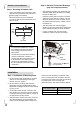
Step 2: Drill Piping Hole 1 Determine hole positions according to the diagram. Drill one (1) hole (Ф55 or Ф70 mm) in the wall at a slight downward slant to the outdoor side. Piping hole Model Ф55 mm Cooling capacity <6000W Cooling capacity >6000W Ф70 mm 2 The inclination must be between 5 - 10mm in order to ensure a good drain of condensed water generated by the indoor unit. Indoor Wall pipe Outdoor Step 3: Installation of Drain Hose 1 Connect the drain hose to the outlet pipe of the indoor unit.
3 Wrap the insulating pipe with wide vinyl tape to prevent the shift of insulating pipe. Slant the drain hose downward slightly for smooth drainage of condensing water. Vinyl tape Outlet pipe of indoor unit Connected Step 4: Installation of Indoor Unit The piping can be output from right, rear right, left or rear left. 1 When routing the piping and wiring from the left or right side of indoor unit, cut off the tailings from the chassis when necessary (see figure below).
• Follow the instruction as below for exchanging the position of drain cap and drain hose in case from left side to right. Piping on the rear right side (a) Pull out the drain cap at the rear right of the indoor unit. Drain cap (b) Pull out the drain hose at the rear left of the indoor unit. Drain hose from the right side Piping on the right side Drain hose Drain hose from the left side (c) Put the drain cap into the drain hole at the rear left of the indoor unit.
• Do not route both refrigerant piping and drain hose from the right side to the left side to prevent big gap between the indoor unit and the wall. Drain hose from the right side Piping and cable from the right side 4 Take out the piping from body case, wrap the piping, power cords, drain hose with the tape and then make them pass through the piping hose. Do not put any object in the drain pan located in the rear of the indoor unit, as the condensed water is gathered there and piped out of the room.
Step 5: Installation of Connection Pipe Flare nut Refrigerant pipe connection Copper tube 1 Flaring work Main cause for refrigerant leakage is due to defects in the flaring work. Carry out correct flaring work using the following procedure: A: Cut the pipes and the cable. • Use the piping kit accessory (if applicable) or pipes purchased locally. • Measure the distance between the indoor and the outdoor unit. • Cut the pipes a little longer than the measured distance. • Cut the cable 1.
Step 6: Piping Connection - Indoor Unit A: Connecting the indoor unit tubing to the connection piping: • B: Wrap the insulation material around the connecting portion: • Align the centers of the pipes and sufficiently tighten the flare nut with your hands first. Cover the indoor unit pipe and the connection pipe with the heat insulation material. Bind them together with vinyl tape so that there is no gap.
Pipe Drain hose Vinyl tape (narrow) Connection power cable Step 7: Piping Connection Outdoor Unit A: Align the centers of the pipes and sufficiently tighten the flare nut with your hands. Wrap with vinyl tape (wide) C: Positioning the indoor unit: • Remove the spacer. • Hook the indoor unit onto the upper portion of the mounting plate (Engage the hooks of the mounting plate into the openings at the rear top of the indoor unit).
B. In cases where the outdoor unit is installed below the indoor unit level: • Wrap the piping, drain hose and connecting cable from the down to up. • Secure the wrapped piping along the exterior wall using saddle or equivalent. Seal small openings around piping with a gum type sealer. Wrapping Pipe Connection cable Drain hose Drain hose Trap is required to prevent water from entering into electrical parts. C.
2 The yellow-green wirewire in airinconditioner is is 2 The yellow-green air conditioner the earthing wirewire which can can not be for for the earthing which notused be used other purposes. Improper earthing maymay cause other purposes. Improper earthing cause electric shock. electric shock. EXM09HV1WI 2640~5275W, Heat Pump models EXM12HV1WI Heat Pump models 3 The earth resistance should accord to the 3 The earth resistance should accord to the national wiring regulation. national wiring regulation.
Installation of Outdoor Electric Wires 1 Remove the handle on the right side plate of outdoor unit by loosening the screw. EXM18HV1WE EXM24HV1WE 2 Take off wire cable clamp. Connect and screw the power connection cable and signal control wire (for heap pump model only) onto the terminal block following corresponding identification numbers and colors on the terminal blocks of indoor and outdoor units. 3 To prevent water from entering, make a trap (“U”) in the connection wires (see page 16).
caution After confirming the above conditions, prepare the wiring as follows: • The screws which fasten the wiring to the terminal block may come loose from vibrations during transportation. B. Check the drainage • Carefully pour a glass of water on the evaporator. • Ensure the water flows through the drain hose of the indoor unit without any leakage and goes out the drain exit. • Check and make sure all screws are well fixed. Otherwise, it could cause burn-out of the wires.
Step 11:Air Purging and Leakage Test Air and moisture in the refrigeration system have undesirable effects as indicated below: • Operation of closing stop valve: Securely tighten the valve stem with a special tool. Then securely tighten the valve stem cap with a spanner or the like. • System pressure increase. Refrigerant • Operating current rise. • Cooling or heating efficiency drops. • Moisture in the refrigeration circuit may freeze and block the capillary tubing.
When Using the Vacuum Pump 1 Completely tighten the flare nuts on A, B, C and D, connect the manifold valve charge hose (blue) to the charge port of the low pressure valve (3-way valve) on the gas pipe side. 2 Connect the other charge hose (yellow) of manifold to the vacuum pump. 3 Fully open the handle Lo of the manifold valve. 4 Open the vacuum pump for vacuumization.
Operation Test 1 Before Operation Test • Connect the hose of manifold valve to the charge port of stop valve on the gas pipe side of the outdoor unit. • Do not switch on power before installation is finished completely. • Close the stop valve on the gas pipe side almost completely. • Electric wiring must be connected correctly and securely. • Fully close the stop valve on the liquid pipe side. • Stop valves of the connection pipes should be fully opened.
Congratulazioni Indice Complimenti e grazie per aver scelto un condizionatore split. È un condizionatore di qualità studiato per un uso pratico e semplice. Congratulazioni .......................................... 24 Prima di iniziare a usare il condizionatore, leggere attentamente il libretto di istruzioni, contenente la descrizione dell’apparecchiatura e delle sue funzioni. Avvertenze per l’installazione ...................
Norme di sicurezza Si prega di tenere a portata questo manuale d'installazione e il manuale dell'utente in fase di installazione. Quindi, conservare in luogo pratico per poterlo consultare in futuro. Avvertenze per l’installazione attenzione All’interno del manuale sono riportati molti consigli utili per il corretto utilizzo e la manutenzione del condizionatore.
Prima dell’installazione Strumenti necessari per l’installazione 1 2 3 4 5 6 7 8 9 Livella Cacciavite Trapano elettrico Punta da trapano cava ( 55 mm/ Set strumenti di svasatura Chiavi torsiometriche specificate Chiave (unione parziale) Un bicchiere di acqua Chiave a testa esagonale (4 mm) 70 mm) 10 11 12 13 14 15 16 17 Rilevatore fughe di gas Pompa a vuoto Collettore calibrato Manuale per l’utente Termometro Multimetro Tagliatubi Nastro di misurazione Oggetti richiesti per l’installazione (Per unità i
Spazio fino al soffitto Unità interna 15 cm al di sopra Descrizione del prodotto Spazio fino alla parete 15 cm al di sopra 15 cm al di sopra 3ma l di so 2,5 m al di sopra pra Spazio fino alla parete Lato di uscita dell'aria Fan Mode Light Turbo Healthy Temp Timer-On Timer-Off 5 Swing Spazio fino al pavimento Clock I feel Eco 50 cm al di sopra Spazio fino all'ostruzione Ingresso aria laterale Spazio fino alla parete 30 cm al di sopra 2 17 m al di 30 a pr so cm ra op i
Istruzioni per l'installazione sul posto 7 Individuare un punto a circa 1 m o più da una TV o da qualsiasi altra apparecchiatura elettrica. Un punto di installazione adatto è di vitale importanza per un funzionamento corretto ed efficace dell'unità. 8 Individuare un punto in cui sia possibile estrarre il filtro con facilità. Evitare i siti in cui: • forti fonti di calore, vapore, gas infiammabile o liquidi volatili vengono emessi.
Installazione sul tetto 1 Se l’unità esterna è installata su un tetto, verificare che sia in piano. 2 Verificare che la struttura del tetto e il metodo di ancoraggio siano adeguati per il collocamento dell’unità. 3 Se l’unità esterna è installata sulla struttura del tetto o sulle pareti esterne, ciò può determinare rumori e vibrazioni eccessivi e la classificazione dell’apparecchiatura come installazione non pratica.
Installazione dell’unità esterna Fase 1: Fissaggio dell'unità esterna • Ancorare l'unità esterna fissando i 4 fori esistenti alla base con 4 bulloni e dadi di 10 mm saldamente (non in dotazione). Posizionare l'unità esterna su una superficie orizzontale in cemento o comunque rigida (mai direttamente su erba o terra).
Piastra di Plate fissaggio Mounting TypeTipo A A Segnoonalthe centro Mark middle of it Sinistra Left 55 mm 55mm 45 45 (Rear piping (Foro tubazioni hole) posteriori) 150 150 605 605 317 317 Spazio Space finothe alla to parete wall 150 mm al 150mm di sopra above 45 45 45 45 Spazio 35 Space 35 finothe alla to parete wall 150 mm al 150mm di sopra Parete Wall above Gradiente Gradienter 6994 6994 Parete Wall Destra Right 55 mm 55mm 45 (Foro tubazioni 45 (Rear piping hole) posteriori) Piastra di Plat
Fase 2: Foro per tubazione 1 Determinare le posizioni dei fori conformemente al diagramma. Fare un (1) foro col trapano (Ф 55 o Ф 70 mm) nella parete, che sia leggermente inclinato verso il basso dal lato uscita. Foro della tubazione Ф 55 mm Ф 70 mm Modello Capacità di raffreddamento < 6000 W Capacità di raffreddamento > 6000 W 2 L'inclinazione deve essere fra 5 - 10 mm per garantire un buono scarico dell'acqua di condensa generata dall'unità interna.
3 Avvolgere la tubazione di isolamento con un nastro vinilico largo per evitare lo spostamento della tubazione. Inclinare leggermente il tubo flessibile di scarico verso il basso per uno scarico fluido dell'acqua di condensa. Nastro vinilico Tubazione di uscita dell'unità interna Collegati Fase 4: Installazione dell'unità interna La tubazione può essere fatta uscire da destra, dalla parte posteriore destra, da sinistra o dalla parte posteriore sinistra.
• Attenersi alle seguenti istruzioni per sostituire la posizione del tappo di scarico e del tubo flessibile di scarico, ove necessario, da sinistra a destra. Tubazione sul lato posteriore destro (a) Estrarre il tappo di scarico sul lato posteriore destro dell'unità interna. Tappo di scarico (b) Estrarre il tubo flessibile di scarico sul lato posteriore sinistro dell'unità interna.
• Non disporre sia la tubazione refrigerante che il tubo flessibile di scarico da destra a sinistra per evitare che vi siano delle distanze troppo elevate fra l'unità interna e la parete. Tubazione e cavo dal lato destro Tubo flessibile di scarico dal lato destro 4 Estrarre le tubazioni dal case del corpo principale, avvolgere le tubazioni, i cavi di alimentazione, il tubo flessibile di scarico con del nastro e poi farli passare attraverso il tubo flessibile.
Fase 5: Installazione del tubo di collegamento Collegamento tubazione refrigerante Dado svasato Tubo in rame 1 Svasatura La principale causa delle fughe di gas refrigerante è dovuta a difetti nella svasatura. Eseguire una corretta svasatura procedendo nel modo seguente: A: Tagliare i tubi e il cavo. • Utilizzare il kit di svasatura (se disponibile) o tubi acquistati localmente. • Misurare la distanza tra l’unità interna e quella esterna.
Fase 6: Collegamento tubazioni Unità interna A: Collegamento delle tubazioni dell'unità interna alla tubazione di collegamento: • B: Avvolgere il materiale isolante attorno alla parte di collegamento: • Allineare come prima cosa centralmente i tubi e unirli serrando manualmente il dado svasato. Tubatura dell’unità interna Coprire il tubo dell'unità interna e il tubo di collegamento col materiale isolante dal calore. Unirli con del nastro vinilico in modo tale che non vi siano interstizi.
Tubo Tubo flessibile di scarico Nastro vinilico (stretto) Cavo di collegamento elettrico Fase 7: Collegamento tubazioni Unità esterna A: Allineare i centri dei tubi e unirli serrando manualmente il dado svasato. Avvolgere di nastro vinilico (largo) C: Individuazione della posizione dell’unità interna: • Rimuovere il distanziale.
B. Qualora l’unità esterna sia installata più in basso dell’unità interna: • Avvolgere con nastro la tubazione, il tubo flessibile di scarico e il cavo di collegamento dal basso verso l’alto. • Fissare la tubazione avvolta nel nastro lungo la parete esterna mediante un dispositivo a sella o equivalente. Sigillare le piccole aperture attorno alla tubazione con sigillante di gomma.
22 IlThe cavo giallo-verdewire nel condizionatore dell'aria yellow-green in air conditioner is èthe il cavo di massa che non usato earthing wire which canpuò notessere be used for per altripurposes. scopi. Una messa a terra eseguita in other Improper earthing may cause modo sbagliato electric shock. può essere causa di scosse elettriche. 3 The earth resistance should accord to the 3 La resistenza diregulation. terra dovrebbe essere in linea national wiring con le normative nazionali sul cablaggio.
Installazione dei cavi elettrici esterni 1 Rimuovere la maniglia sulla piastra del lato destro dell'unità interna allentando la vite. EXM18HV1WE EXM24HV1WE Maniglia 2 Estrarre la morsettiera. Collegare e avvitare il cavo di collegamento elettrico e il cavo di controllo del segnale (solo per i modelli con pompa di calore) al blocco terminali seguendo i numeri e i colori di identificazione sui blocchi terminali delle unità interne ed esterne.
attenzione Dopo avere confermato le condizioni precedenti, preparare i cavi nel modo seguente: • Le viti che serrano il cablaggio alla morsettiera si potrebbero allentare a causa di vibrazioni in fase di trasporto. B. Verifica dello scarico • Versare un bicchiere di acqua sull’evaporatore. • Verificare che l’acqua scorra attraverso il tubo flessibile di scarico dell’unità interna senza nessuna perdita e che fuoriesca dall’uscita di scarico. • Verificare che tutte le viti siano saldamente fissate.
Fase 11: Spurgo aria e test perdite L’aria e l’umidità del sistema refrigerante hanno i seguenti effetti indesiderati: • Aumento della pressione del sistema. • Chiusura della valvola di stop: Serrare saldamente lo stelo della valvola con uno strumento speciale. Quindi, fissare saldamente il coperchio dello stelo della valvola usando una chiave per dadi o altro attrezzo simile. Refrigerante • Aumento della corrente operativa. • Calo dell’efficienza di raffreddamento o riscaldamento.
Quando di usa la pompa a vuoto 1 Serrare completamente i dadi svasati, A, B, C, D, collegare il tubo di carico della valvola del collettore (blu) a una presa di carico della valvola di riempimento a bassa pressione (valvola a 3 vie) sul lato del tubo del gas. 2 Collegare l'altro tubo flessibile di carico (giallo) del collettore alla pompa a vuoto. 3 Aprire completamente la maniglia a bassa pressione della valvola del collettore. 4 Aprire la pompa a vuoto per l'operazione di estrazione aria.
Test di funzionamento 1 Prima del test di funzionamento • Collegare il tubo flessibile della valvola del collettore alla porta di carico della valvola di stop sul lato tubo del gas dell'unità esterna. • Non accendere prima di aver completato l'installazione. • Chiudere la valvola di stop sul lato tubo del gas quasi completamente. • Il cablaggio elettrico deve essere collegato in modo giusto e sicuro. • Chiudere completamente la valvola di stop sul lato del tubo liquido.
Enhorabuena Contenido Le damos la enhorabuena y las gracias por elegir un acondicionador de aire de tipo split. Estamos seguros de que le resultará un placer usar su nuevo acondicionador de aire. Enhorabuena .............................................. 46 Antes de utilizarlo, le recomendamos que lea atentamente todo el manual del usuario, en el que se ofrece la descripción del acondicionador de aire y sus funciones.
Precauciones de seguridad Lea atentamente este manual de instalación y el manual del usuario antes de instalarlo y guárdelo con cuidado a mano para futuras consultas. En su interior encontrará muchas sugerencias válidas sobre cómo utilizar y mantener debidamente su acondicionador de aire. Los trabajos eléctricos deben realizarse por electricistas cualificados. Asegúrese de utilizar la calibración correcta del enchufe y el circuito principal para el modelo que se va a instalar.
Antes de la instalación Herramientas necesarias para la instalación 1 2 3 4 5 6 7 8 9 Indicador de nivel Destornillador Taladro eléctrico Broca de corona ( 55 mm / 70 mm).
Espacio hasta el techo Espacio hasta la pared 15 cm por encima Espacio hasta la pared 2,5 m por encima ima 15 cm por encima 3mp or en c Lado de salida de aire Fan Mode Light Turbo Healthy Temp Timer-On Timer-Off 5 Swing Espacio hasta el suelo Clock I feel Eco Espacio para obstrucción 50 cm por encima Interior interior 15 cm por encima Descripción del producto Lado de entrada de aire Espacio hasta la pared a 30 cm por encima 30 2 17 m im nc re po a cm r po cim en 50
Instrucciones del lugar de instalación Un lugar de instalación adecuado es esencial para el funcionamiento correcto y eficaz de la unidad. Evite lugares donde: • se emitan fuertes fuentes de calor, vapores, gases inflamables o líquidos volátiles. • se generen ondas electromagnéticas de alta frecuencia por equipos de radio, soldadores o equipos médicos. • exista aire salino (por ejemplo, cerca de la costa). • el aire esté contaminado con aceites y vapores industriales.
Instalación en el tejado 1 Si instala la unidad exterior en un tejado, asegúrese de colocarla a nivel. 2 Asegúrese de que la estructura del tejado y el sistema de anclaje son adecuados para la ubicación de la unidad. 3 Si la unidad exterior se instala en estructuras de tejados o muros exteriores, puede generar ruido y vibraciones excesivos, y también considerarse una instalación que no puede recibir servicio.
Instalación de la unidad exterior Paso 1: Fijación de la unidad exterior • Paso 2: D esagüe de condensado exterior (solo para modelo con bomba de calor) Ancle la unidad exterior con los 4 orificios existentes en su base con 4 pernos y tuercas de 10 mm firmemente (no incluidos). • Coloque la unidad exterior sobre una superficie horizontal de cemento o rígida (nunca directamente sobre cristal ni tierra).
Tipo de placa montaje A Mounting PlatedeType A Espacio Space hasta la to the pared wall 150 mm por 150mm encima Pared above Marcaonenthe el middle centro of it Mark 35 35 150 150 605 605 317 317 Espacio Space hasta la to the pared 150 mm wall por 150mm encima above 45 45 45 45 Wall Izquierda Left 55 mm 55mm 45 45 (Rear piping (Orificio de tubohole) trasero) Inclinación Gradienter 6994 6994 Pared Wall Derecha Right 55 mm 55mm 45(Orificio de tubo trasero) 45 (Rear piping hole) Tipo de placa mo
Paso 2: Taladre el orificio del tubo 1 Determine las posiciones de los orificios de acuerdo con el diagrama. Taladre un (1) orificio (Ф 55 o Ф70 mm) en la pared con una ligera inclinación al lado exterior. Orificio del tubo Modelo Ф 55 mm Capacidad de enfriamiento < 6.000 W Ф 70 mm Capacidad de enfriamiento > 6.000 W 2 La inclinación debe ser de 5 - 10 mm para poder garantizar un correcto drenaje del agua de condensación generada por la unidad interior.
3 Envuelva el tubo de aislamiento con cinta de vinilo para evitar que se desplace el tubo. Incline ligeramente el tubo de desagüe hacia abajo para que el agua de condensación se drene suavemente. Cinta de vinilo Tubo de salida de la unidad interior Conectado Paso 4: Instalación de la unidad interior El tubo se puede sacar de la derecha, derecha posterior, izquierda o izquierda posterior.
• Siga las instrucciones siguientes para cambiar la posición del tapón y el tubo de desagüe en el caso del lado izquierdo al derecho. Tubo del lado trasero derecho (a) Tire del tapón en la parte trasera derecha de la unidad interior. Tapón de desagüe (b) Tire del tubo en la parte trasera izquierda de la unidad interior.
• No coloque el tubo de refrigerante y el de desagüe del lado derecho al izquierdo para evitar que quede un gran hueco entre la unidad interior y la pared. Tubo de desagüe del lado derecho Tubo y cable del lado derecho 4 Saque el tubo de la carcasa, envuelva el tubo, los cables de alimentación y el tubo de desagüe con la cinta y páselos después por la manguera.
Paso 5: Instalación del tubo de conexión Tuerca acampanada Conexión del tubo de refrigerante Tubo de cobre 1 Trabajo de acampanado La causa principal de las fugas de refrigerante son defectos de acampanado. Realice un acampanado correcto siguiendo este procedimiento: A: Corte los tubos y el cable. • Utilice el accesorio de kit de tubos (si es preciso) o tubos adquiridos localmente. • Mida la distancia entre la unidad interior y la exterior. • Corte los tubos algo más largos que la distancia medida.
Paso 6: Conexión del tubo unidad interior B: Envuelva el material aislante alrededor de la parte conectada: A: Conexión de los tubos de la unidad interior al tubo de conexión: • • Alinee los centros de los tubos y apriete primero a mano suficientemente la tuerca acampanada. Tuerca acampanada Tubo de la unidad interior Bridas para cables Material aislante Tubos • Llave dinamométrica Llave inglesa Cubra el tubo de conexión de la unidad interior y el de conexión con el material aislante térmico.
Tubo Manguera de desagüe Cinta de vinilo (estrecha) Cable de alimentación de conexión Envuelva con cinta de vinilo (ancha) Paso 7: Conexión del tubo - unidad exterior A: Alinee los centros de los tubos y apriete suficientemente a mano la tuerca acampanada. C: Posición de la unidad interior: • Retire el separador. • Enganche la unidad interior en la parte superior de la placa de montaje (introduzca los ganchos de la placa en las aberturas de la parte posterior superior de la unidad interior).
B. Si la unidad exterior está instalada por debajo de la unidad interior: • Envuelva los tubos, la manguera de desagüe y el cable de conexión de abajo a arriba. • Fije los tubos envueltos a lo largo de la pared exterior utilizando bridas o similares. Selle las pequeñas aberturas en torno a los tubos con un sellador elástico. Envoltorio Tubo Cable de conexión Manguera de desagüe Manguera de desagüe Hace falta un bucle para que el agua no llegue a los componentes eléctricos. C.
22 ElThe cable amarillo-verde acondicionador yellow-green wire del in air conditioner is de es un wire cablewhich de conexión theaire earthing can not abetierra usedque for no se puede utilizar con otros fines. may Una cause other purposes. Improper earthing conexión a tierra incorrecta puede causar electric shock. descargas eléctricas. 3 The earth resistance should accord to the 3 La resistencia tierra debe cumplir la national wiringa regulation. normativa nacional de cableado.
Instalación de los cables eléctricos de la unidad exterior 1 Retire el asa de la placa lateral derecha de la unidad exterior aflojando el tornillo. EXM18HV1WE EXM24HV1WE Mango 2 Saque la abrazadera del cable. Conecte y atornille el cable de conexión de alimentación y el de control de señal (sólo para modelo con bomba de calor) a la regleta siguiendo los números de identificación correspondientes y los colores de las regletas de las unidades interior y exterior.
precaución Tras confirmar las condiciones anteriores, prepare el cableado como sigue: • Los tornillos que sujetan los cables a la regleta pueden haberse aflojado por las vibraciones durante el transporte. B. Comprobación del desagüe • Vierta con cuidado un vaso de agua en el evaporador. • Asegúrese de que el agua fluya por la manguera de desagüe de la unidad interior sin fugas y que salga por el desagüe. • Asegúrese de que todos los tornillos están bien apretados.
Paso 11: Prueba de fugas y purga de aire El aire y la humedad tienen efectos dañinos para el sistema de refrigeración, como se indica más adelante: • Funcionamiento de la válvula de cierre: Apriete con firmeza el vástago de la válvula con una herramienta especial. A continuación apriete de forma segura la tapa del vástago de la válvula con una llave inglesa o similar. Refrigerante • Aumento de la presión del sistema. • Aumento de la corriente de funcionamiento.
Cuando utilice la válvula de vacío 1 Apriete completamente las tuercas acampanadas en A, B, C y D, conecte la manguera de carga de la válvula de colector (azul) a un puerto de carga de la válvula de baja presión (3 vías) del lado del tubo de gas. 2 Conecte el otro tubo de carga (amarillo) del colector a la bomba de vacío. 3 Abra por completo la manilla “Lo” de la válvula de colector. 4 Abra la bomba de vacío para la aspiración.
Prueba de funcionamiento 1 Antes de la prueba de funcionamiento • Conecte la manguera de la válvula de colector al puerto de carga de la válvula de cierre en el lado del tubo de gas de la unidad exterior. • No encienda la alimentación antes de que haya terminado completamente la instalación. • Cierre la válvula del lado del tubo de gas casi completamente. • El cableado eléctrico debe conectarse de forma correcta y segura. • Cierre completamente la válvula del lado del tubo de líquido.
Tebrikler İçindekiler Split tipi klima seçtiğiniz için tebrik ve teşekkür ederiz. Yeni klimanızı kullanmanın bir zevk olduğunu hissedeceğinizden eminiz. Tebrikler ....................................................... 68 Klimayı kullanmadan önce, klima ve fonksiyonlarının açıklandığı kullanma kılavuzunun tümünü okumanızı öneririz. Montaj Uyarısı .............................................
Güvenlik önlemleri Bu montaj kılavuzunu ve kullanma kılavuzunu montaj öncesinde hazırlayın ve daha sonraki başvurular için erişimi kolay bir yerde saklayın. Bu kılavuz içinde, klimanızı kullanımı ve bakımı hakkında size yardımcı olabilecek yararlı ipuçları bulacaksınız. Elektrik işleri kalifiye bir elektrik teknisyeni tarafından yapılmalıdır. Monte edilecek model için doğru değerde güç fişi ve ana iletim devresi kullandığınızdan emin olun.
Montajdan Önce Montaj için Gerekli Aletler 1 2 3 4 5 6 7 8 9 Seviye ölçer Tornavida Elektrikli matkap Delik matkabı ( 55 mm / Rayba seti Ayarlı tork anahtarları Anahtar (yarım rakor) Bir bardak su Altıgen anahtar (4 mm) 70 mm) 10 11 12 13 14 15 16 17 Gaz kaçağı dedektörü Vakum pompası Sayaç manifoldu Kullanma kılavuzu Termometre Multimetre Boru kesici Ölçüm bandı Montaj için gerekli öğeler (Her bir iç ve dış ünite için) Numara Aksesuarların Adı İç mekan ünitesi montaj plakası Klips ankrajı Kendinden k
Tavana olan mesafe İç Mekan Ünitesi 15 cm yukarı Ürün Tanımı Duvara olan mesafe 15 cm yukarı 15 cm yukarı 3my ukarı 2,5 m yukarı Duvara olan mesafe Hava çıkış tarafı Fan Mode Light Turbo Healthy Temp Timer-On Timer-Off 5 Swing Zemine olan mesafe Clock I feel Eco 50 cm yukarı Tıkanma alanı Duvara olan mesafe 30 cm yukarı 30 rı 50 cm yukarı ka m yu Duvara olan mesafe 2 Hava çıkış tarafı 17 cm Hava giriş tarafı rı ka u y Dış Ünite 15 16 71
7 Bir TV seti ya da başka bir elektrikli cihazdan yaklaşık 1m ya da daha uzakta bir yer seçin. Montaj Yeri Talimatı 8 Filtrenin kolayca çıkarılabileceği bir yer seçin. Ünitenin doğru ve etkin şekilde çalışması için uygun montaj yerinin seçilmesi hayati önem taşır. 9 Üniteyi çamaşırhanede ya da havuz başında kullanmayın. Aşağıdaki özelliklere sahip yerlerden kaçının: 10 Titreşim ve gürültüyü asgari düzeye indirmek için en az 3 metre uzunluğunda bir boru gereklidir.
Tavan Üzeri Montaj 1 Dış ünite tavan üzerine monte edilirse, ünitenin düz konumda durmasını sağlayın. 2 Tavan yapısı ve ankraj metodunun ünite konumuna uygun olduğundan emin olun. 3 Dış ünite tavana ya da dış duvara takılırsa, bu durum aşırı gürültü ve titreşime neden olabilir ve “servis yapılamaz montaj” olarak sınıflandırılabilir.
Dış Ünite Montajı Adım 1: Dış Ünitenin Sabitlenmesi • Dış mekan ünitesini, üzerinde bulunan 4 deliğe 10 mm çapındaki 4 cıvata ve somunu geçirip sıkmak suretiyle sabitleyin (pakete dahil değildir). Dış mekan ünitesini katı veya sert bir yüzey üzerine yerleştirin (asla doğrudan çimen veya arazi üzerine koymayın). Adım 2: Dış Yoğuşma Tahliyesi (sadece ısı pompalı model için) • Isıtma işlemi sırasında, yoğuşma ve buz çözme suyunun tahliye hortumundan düzgün şekilde tahliye edilmesi gerekir.
A Tipi Montaj Plakası Mounting Plate Type A Orta kısmını işaretleyin Mark on the middle of it Duvar Wall Duvara 35 Space olan to the mesafe wall 150 mm 150mm yukarı above 150 605 Duvara Space olan to the mesafe wall 150 mm 150mm yukarı above Duvar Wall Sağ Right 55 mm 55mm 45 (Rear (Arka boru pipingdeliği) hole) 45 45 Sol Left 55 mm 55mm (Arka boru (Rear pipingdeliği) hole) 45 Eğimölçer Gradienter 317 6994 B Tipi Montaj Plakası Mounting Plate Type B Mounting Plate Type C Mounting Plate Type D
Adım 2: Boru için Delik Açın 1 Şemaya göre delik konumlarını belirleyin. Dış mekan tarafına doğru hafif eğimli olacak şekilde duvara bir (1) delik (Ф55 ya da Ф70 mm) açın. Boru deliği Ф55 mm Ф70 mm Model Soğutma kapasitesi < 6000 W Soğutma kapasitesi > 6000 W Her iki desteği de çıkarın 2 İç mekan ünitesinin ürettiği yoğuşma suyunun iyi tahliye edilebilmesi için eğimin 5 - 10 mm arasında olması gerekir.
3 Yalıtkan borunun kaymasını önlemek için yalıtkan boruyu geniş vinil bant ile sarın. Yoğuşma suyunun iyi tahliye edilebilmesi için tahliye hortumunu aşağı doğru eğin. İzolasyon bandı İç mekan ünitesinin çıkış borusu Bağlandı Adım 4: İç Mekan Ünitesinin Montajı Borular, sağdan, arka sağdan, soldan ya da arka soldan çıkarılabilir. 1 Boruları ve kabloyu iç mekan ünitesinin solundan ya da sağından geçirirken, gerektiğinde kuyrukları gövdeden kesin (aşağıdaki şekle bakın).
• Tahliye kapağı ve tahliye hortumunun konumunu soldan sağa almanız gerektiğinde aşağıdaki talimatları takip edin. Sağ arka taraftaki borular (a) İç mekan ünitesinin sağ arka kısmından tahliye kapağını çıkarın. Tahliye kapağı (b) İç mekan ünitesinin sol arka kısmından tahliye hortumunu çıkarın. Sağ taraftan tahliye hortumu Sağ taraftaki borular Tahliye hortumu Sol taraftan tahliye hortumu (c) Tahliye kapağını iç mekan ünitesinin sol arka kısmındaki tahliye deliğine takın.
• İç mekan ünitesi ile duvar arasında büyük boşluk oluşmasını önlemek için soğutucu gaz borusu ile tahliye hortumunu sağdan sola aktarmayın. Sağ taraftan tahliye hortumu Sağ taraftan borular ve kablolar 4 Boruları gövde muhafazasından çıkarın, boruları, elektrik kablolarını ve tahliye hortumunu bant ile sarın ve bunları boru hortumundan geçirin. Yoğuşmuş su burada toplandıktan sonra odadan dışarı çıktığı için iç mekan ünitesinin arkasındaki tahliye kabına herhangi bir cisim koymayın.
Adım 5: Bağlantı Borusunun Montajı Konik cıvata Soğutucu gaz borusunun bağlanması Bakır boru 1 Rayba işi Soğutucu gaz kaçağının ana nedeni raybalama hatalarıdır. Aşağıdaki prosedürü kullanarak doğru raybalama işlemini yapın: A:Boruları ve kabloyu kesin. • Yerel olarak satılan boru kiti aksesuarını (varsa) ya da boruları kullanın. • İç mekan ünitesi ile dış ünite arasındaki mesafeyi ölçün. • Boruları ölçülen mesafeden biraz daha uzun kesin. • Kabloyu boru uzunluğundan 1,5 m daha uzun kesin.
Adım 6: Boru bağlantısı - İç Mekan Ünitesi A: İç mekan ünitesi borusunun bağlantı borusuna bağlanması: • B: Yalıtım malzemesini bağlantı kısmının etrafına sarın: • Boruların merkezlerini hizalayın ve konik cıvatayı önce elinizle yeterince sıkın. İç mekan ünitesi borusunu ve bağlantı borusunu ısı yalıtım malzemesi ile kaplayın. Boşluk olmayacak şekilde vinil bant ile bunları bağlayın.
Boru Tahliye hortumu İzolasyon bandı (dar) Bağlantı güç kablosu Adım 7: Boru Bağlantısı - Dış Ünite A: Boruların merkezlerini hizalayın ve konik cıvatayı elinizle yeterince sıkın. İzolasyon bandı (geniş) ile sarın C: İç mekan ünitesinin konumlandırılması: • Ara parçayı çıkarın. • İç mekan ünitesini montaj plakasının üst kısmına geçirin (Montaj plakasının kancalarını iç mekan ünitesinin arka üst kısmındaki açıklıklara geçirin).
B. Dış ünitenin iç mekan ünitesi seviyesinin altına takılacağı durumlarda: Adım 9: Elektrik Tesisatı • Boruları, tahliye hortumunu ve bağlantı kablosunu aşağıdan yukarıya doğru sarın. Güvenlik Önlemleri • Sarılan boruları altlık ya da benzeri bir malzeme kullanarak dış duvar boyunca sabitleyin. Montaja başlamadan önceki elektrik güvenlik kuralları: Kauçuk türü bir yalıtkan ile boru çevresindeki küçük açıklıkları kapatın.
uygun 3 Theolmalıdır. earth resistance should accord to the national wiring regulation. 4 Kullanıcı elektriğinde güvenilir bir topraklama terminali bulunmalıdır. Topraklama kablosunu 4 The user’s power must have reliable earthing aşağıdakiler terminal.
Dış Ünite Elektrik Kablolarının Montajı 1 Vidayı gevşeterek dış ünitenin sağ plakasındaki kolu çıkarın. EXM18HV1WE EXM24HV1WE Kol 2 Tel kablo kelepçesini çıkarın. İç ve dış ünitenin terminal bloklarındaki tanımlama numaralarını ve renklerini takip ederek güç bağlantı kablosunu ve sinyal kontrol telini (sadece ısı pompalı model için) terminal bloğuna takıp vidalayın. 3 Su girişini önlemek için, bağlantı tellerinde bir kapan (“U”) yapın (bkz. sayfa 16).
dikkat Yukarıdaki koşulları sağladıktan sona, kabloyu aşağıdaki gibi hazırlayın: • Kabloları terminal bloğuna bağlayan vidalar taşıma sırasındaki titreşim sebebiyle gevşeyebilir. B. Tahliyeyi kontrol edin • Evaporatöre dikkatli bir şekilde bir bardak su boşaltın. • Herhangi bir kaçak veya tahliye olmadan suyun iç mekan ünitesinin tahliye hortumundan aktığından emin olun. • Tüm vidaların iyice sıkıldığını kontrol edin. Aksi takdirde, kabloların yanmasına neden olabilir.
Adım 11: Hava Tahliyesi ve Kaçak Testi Soğutma sistemindeki hava ve nemin aşağıda belirtildiği gibi istenmeyen etkileri vardır: • Kapatma stop valfinin çalışması: Valf gövdesini özel bir alet ile iyice sıkın. Valf gövdesi kapağını bir anahtar ya da benzeriyle iyice sıkın. • Sistem basıncında artış. Soğutucu gaz • Çalışma akımında artış. • Soğutma ya da ısıtma veriminde azalma. • Soğutucu devredeki nem donarak ince tüpü tıkayabilir.
Test ve Çalıştırma Vakum Pompasını Kullanırken 1 Konik cıvataları A, B, C ve D üzerinde tam olarak sıkın, manifold valfı dolum hortumunu (mavi) gaz borusu tarafındaki düşük basınç valfına (3-yollu valf) takın. 2 Manifoldun diğer dolum hortumunu (sarı) vakum pompasına takın. 3 Manifold valfının Düşük kolunu tam olarak açın. 4 Vakumlama için vakum pompasını açın.
Çalışma Testi 1 Çalıştırma Testi Öncesinde • Montaj tam olarak bitmeden gücü açmayın. • Elektrik kablosu düzgün ve sıkı şekilde takılmalıdır. • Bağlantı borularının stop valfleri tam olarak açılmalıdır. • Atık maddeler gibi tüm parçacıkların üniteden çıkarılması gerekir. 2 Çalışma Testi Metodu • Çalıştırmak için gücü açın ve uzaktan kumandadaki “ON/OFF” düğmesine basın. • MODE düğmesine basarak tüm işlevlerin düzgün çalıştığını kontrol etmek için SOĞUTMA, ISITMA (varsa), FAN öğelerini seçin.
www.electrolux.