SERVICE MANUAL AIR CONDITIONER Electrolux Home Products Italy S.p.A. Corso Lino Zanussi, 30 I - 33080 Porcia – PN Fax: + 39 0434 394096 Publication number 599 76 28-75 EN Edition: 01-2013 Rev 0.
CONTENTS 1. Precaution ............................................................................................................................................. 1 1.1 Safety Precaution. .............................................................................................................................. 1 1.2 Warning ............................................................................................................................................... 1 2.
1. Precaution 1.1 Safety Precaution. To prevent injury to the user or other people and property damage, the following instructions must be followed. Incorrect operation due to ignoring instruction will cause harm or damage. Before service unit, be sure to read this service manual at first. 1.2 Warning Installation Do not use a defective or underrated circuit breaker. Use this appliance on a dedicated circuit. There is risk of fire or electric shock.
It may cause injury, accident, or damage to the product. Be sure the installation area does not deteriorate with age. If the base collapses, the air conditioner could fall with it, causing property damage, product failure, and personal injury. Do not let the air conditioner run for a long time when the humidity is very high and a door or a window is left open. Moisture may condense and wet or damage furniture. Take care to ensure that power cable could not be pulled out or damaged during operation.
unit is so equipped.) There is risk of physical injury, electric shock, or product failure. When the product is soaked (flooded or submerged), contact an Authorized service center. There is risk of fire or electric shock. Be caution that water could not enter the product. There is risk of fire, electric shock, or product damage. Ventilate the product from time to time when operating it together with a stove, etc. There is risk of fire or electric shock.
Operational. Do not expose the skin directly to cool air for long periods of time. (Do not sit in the draft). This could harm to your health. Do not use the product for special purposes, such as preserving foods, works of art, etc. It is a consumer air conditioner, not a precision refrigerant system There is risk of damage or loss of property. Do not block the inlet or outlet of air flow. It may cause product failure. Use a soft cloth to clean. Do not use harsh detergents, solvents, etc.
2. Function and control panel 2.1 Function ※ Operation mode: Cooling, Heating, Dry, Fan and Auto. ※ ION (optional) ※ Auto swing function. ※ Timer function. ※ Flexible installation kit. ※ No bucket design. ※ LED display. ※ Sleep mode. ※ Follow me function.(Optional) ※ Washable filter. ※ Self-diagnosis and auto-protection function. ※ Anti-freezing control in cooling or drying mode. Prevent the water being freezed on evaporator by sensing the evaporator pipe temperature in cooling or drying mode.
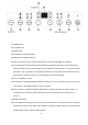
(1) POWER button Power switch on/off (2) SLEEP button Used to initiate the SLEEP operation. (3) FAN/ION button (ION is optional) Control the fan speed. Press to select the fan speed in four steps-LOW, MED, HI and AUTO. The fan speed indicator light illuminates under different fan settings except AUTO speed. When select AUTO fan speed, all the fan indicator lights turn dark. NOTE: Press this button for 3 seconds to initiate ION feature.
(6) Timer button Used to initiate the AUTO ON start time and AUTO OFF stop time program, in conjuction with the (+)&(-) buttons. The timer on/off indicator light illuminates under the timer on/off settings. (7) SWING button (Applicable to the models with auto swing feature only) Use to initiate the Auto swing feature when the operation is ON, press the SWING button can stop the louver at the desired angle. (8) LED Display Show the set temperature in "℃" or "℉" and the Auto-timer settings.
3.
4 Refrigerant Cycle Diagram The figure below is a brief description of the important components and their function in what is called the refrigeration system. (1) This will help to understand the refrigeration cycle and the flow of the refrigerant in the cooling cycle.
(2).This figure below is fit for Heat Pump Unit.
5 Wiring Diagram EXP09CN1W2,EXP09CN1W5 202025490744 11
EXP09HN1WI, EXP12HN1WI,EXP09HN1W5, 202025490732 12
6 Electronic function 6.1 Terms and definitions TC: Temperature of evaporator (T2). TA: Temperature of indoor ambient (T1). TS: The set temperature. TE: Temperature of condenser (T3) 6.2 Electric Control working environment Input voltage: 187~264V for 50Hz models and 97~127V for 60Hz models; 6.3 Protection function 6.3.1 The compressor functions protection with a delay of three minutes. 6.3.2 Sensor protection at open or short circuit. 6.3.3 Evaporator anti-icing protection at cooling mode.
Operation conditon Compressor on (TA-Ts)℃ +1 0 Compressor off 6.5.2.1 If TA﹥TS+1℃, the outdoor fan operates. After 15 seconds, the compressor operates. 6.5.2.2 The compressor is on, if TA≤TS, this compressor will stop. If the outdoor fan operates for 3 minutes at least, it will stop after delaying for 5 seconds. 6.5.3. When the unit is off, the compressor stops at first, and the indoor/outdoor fan will stop after delaying for 5seconds.
6.6.3. The ION/TIMER functions are valid at the drying mode. 6.7 Heating mode 6.7.1. The speed of indoor fan can be optionally chosen as High/Mid/Low. The compressor and outdoor fan keep on stop (except P1 protection) 6.7.2. At heating mode, the heater will operate according to the difference between TA and TS. Electric heater operates as below. Operation conditon (TA-Ts)℃ Heater off +1 0 Heater on 6.7.2.1. When TA﹤TS, the indoor fan operates firstly, and then the heater operates after 4 seconds. 6.7.
6.9 Some standard functions synopsis 6.9.1. Timer function When the unit is on, press the Timer button will initiate the Auto-off stop program, the TIMER OFF indicator light illuminates. Press the UP or down button to select the desired time. Press the TIMER button again within 5 seconds, the Auto-on start program is initiated. And the TIMER ON indicator light illuminates. Press the up or down button to select the desired Auto-on start time.
7 Installation details 7.1 Installation instructions Location The air conditioner should be placed on a firm foundation to minimize noise and vibration. For safe and secure positioning, place the unit on a smooth, level floor strong enough to support the unit. The unit has casters to aid placement, but it should only be rolled on smooth, flat surfaces. Use caution when rolling on carpet surfaces. Do not attempt to roll the unit over objects.
Note: If the window opening is less than the mentioned minimum length of the window slider kit, cut that one with a hole in it short to fit for the window opening. Do never cut out the hole in window slider kit.
A a B b Type I 67.5 2.22 123 4.04 Type II 56.2 1.84 98.2 3.22 Installation in a double-hung sash window 1. Cut the foam seal (adhesive type) to the proper length and attach it to the window stool. Fig.4 2. Attach the window slider kit to the window stool. Adjust the length of the window slider kit according to the width of window, shorten the adjustable window kit if the width of window is less than 26.5 (Type I) or 22.
C Type I 26.5"~48.0" Type II 22.1"~38.6" 3. Cut the foam seal (adhesive type) to the proper length and attach it on the top of the window. Show as in Fig.6 4. Close the window sash securely against the window. 5. Cut the foam seal to an appropriate length and sealing the open gap between the top window sash and outer window sash. Show as in Fig.7 Installation in a sliding sash window 1. Cut the foam seal (adhesive type) to the proper length and attach it to the window frame. See Fig.8.
2. Attach the window slider kit to the window stool. Adjust the length of the window slider kit according to the width of window. Short the adjustable window kit if the width of window is less than 26.5(Type I) or 22.1(Type II) inches. Open the window sash and place the window slider kit on the window stool. See Fig.9 3. Cut the foam seal (adhesive type) to the proper length and attach it on the top of the window. Show as in Fig.10.
4. Close the sliding sash securely against the window. 5. Cut the foam seal to an appropriate length and sealing the open gap between the top window sash and outer window sash. Show as in Fig.11. Exhaust hose installation The exhaust hose and adaptor must be installed or removed in accordance with the usage mode. Cool, Heat(heat pump type) or Auto mode Install Fan, dehumidify or heat(electrical heat type) mode Remove 1. Install the window Exhaust adaptor B onto the exhaust hose as shown in Fig.
previous pages for window kit installation. 2. Insert the hook of the Exhaust hose into the hole seat of the air outlet and slide down the Exhaust hose along the arrow direction for installation (See Fig.14) The exhaust hose can be installed into the wall (Not applicable to the units without adaptor A, expansion plugs and wooden screws of Accessories). 1. Prepare a hole in the wall.
Note: Cover the hole using the adaptor cap when not in use. The duct can be compressed or extended moderately according to the installation requirement, but it is desirable to keep the duct length to a minimum. IMPORTANT: DO NOT OVER BEND THE DUCT (SEE Fig.16) Water drainage -During dehumidifying modes, remove the drain plug from the back of the unit, install the drain connector(5/8〞universal female mender) with 3 /4〞hose(locally purchased).
drain connector, just attach the drain hose to the hole. Place the open end of the hose directly over the drain area in your basement floor. Please refer to Fig.17&18. -During heating pump mode, remove the lower drain plug from the back of the unit, install the drain connector (5/8 〞 universal female mender) with 3/4 〞 hose(locally purchased). For the models without drain connector, just attach the drain hose to the hole.
-When the water level of the bottom tray reaches a predetermined level, the unit beeps 8 times, the digital display area shows "P1". At this time the air conditioning/dehumidification process will immediately stop. However, the fan motor will continue to operate (this is normal). Carefully move the unit to a drain location. Remove the bottom drain plug and let the water drain away (see above Fig.20). Restart the machine until the "P1" symbol disappears. If the error repeats, call for service.
3. Unit idle for a long time ※Remove the rubber plug at the back of the unit and attach a hose to drain outlet. Place the open end of the hose directly over the drain area in your basement floor (See below Fig.23). ※Remove the plug from the bottom drain outlet, all the water in the bottom tray would drain out (See below Fig.23) ※Keep the appliance running on FAN mode for half a day in a warm room to dry the appliance inside and prevent mold forming.
8 Basic test procedure 8.1 Defective compressor Compressors are single phase, depending on the model unit. All compressor motors are permanent split capacitor type using only a running capacitor across the start and run terminal. All compressors are internally spring mounted and externally mounted on rubber isolators. 8.1.1 Compressor wiring test Remove compressor terminal box cover and disconnect wires from terminals.
The reason for compressor inefficiency is normally due to broken or damaged suction and/or discharge valves, reducing the ability of the compressor to pump refrigerant gas. This condition can be checked as follows: 1. Install a piercing valve on the suction and discharge or liquid process tube. 2. Attach gauges to the high and low sides of the system. 3. Start the system and run a “cooling or heating performance test.” If test shows: A. Below normal high side pressure. B. Above normal low side pressure. C.
connected in series with the common motor terminal. Should the internal temperature and/or current draw become excessive; the contacts in the overload will open, turning off the compressor? The overload will automatically reset, but may require several hours before the heat is dissipated. 8.1.7 Checking the internal overload 1. No power to unit, remove the leads from the compressor terminals. 2. Using an ohmmeter, test continuity between terminals C-S and C-R.
8.2.3 Hermetic compressor replacement. The following procedure applies when replacing components in the sealed refrigeration circuit or repairing refrigerant leaks. (Include Compressor, condenser, evaporator, capillary tube, refrigerant leaks, etc.) 1. Recover the refrigerant from the system at the process tube located on the high side of the system by installing a line tap on the process tube. Apply gauge from process tube to EPA approved gauges from process tube to EPA approved recovery system.
1. Recover all refrigerant and oil from the system. 2. Remove compressor, capillary tube and filter drier from the system. 3. Flush evaporator condenser and all connecting tubing with dry nitrogen or equivalent, to remove all contamination from system. Inspect suction and discharge line for carbon deposits. Remove and clean if necessary. 4. Reassemble the system, including new drier strainer and capillary tube. 5. Proceed with processing as outlined under hermetic component replacement. 8.2.
1. Determine that capacitor is serviceable. 2. Disconnect fan motor wires from fan speed switch or system switch. 3. Apply "live" test cord probes on black wire and common terminal of capacitor. Motor should run at high speed. 4. Apply "live" test cord probes on red wire and common terminal of capacitor. Motor should run at low speed. 5. Apply "live" test cord probes on each of the remaining wires from the speed switch or system switch to test intermediate speeds. 8.
and then gradually move back to infinity. 4. Reverse the leads of the probe and momentarily touch the capacitor terminals. The deflection of the pointer should be two times that of the first check if the capacitor is good. 5. Repeat steps 3 and 4 to check fan motor capacitor. NOTE: A shorted capacitor will indicate a low resistance and the pointer will move to the "0" end of the scale and remain there as long as the probes are connected.
10 Troubleshooting In general, possible trouble is classified in three kinds. One is called Starting Failure which is caused from an electrical defect, another is ineffective Air Conditioning caused by a defect in the refrigeration circuit and improper application, and the other is called the Structure Damage. TROUBLES POSSIBLE CAUSES SUGGEST REMEDIES P1 appears in the display window Drain the water in the bottom tray. Room temperature is lower than the set temperature.
PPD_121107_A(50Hz, 60Hz) 36