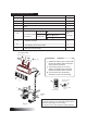
ROOM AIR CONDITIONER INSTALLATION MANUAL (Split Type) Please read this installation manual completely before installing the product. When the power cord is damaged, replacement work shall be performed by authorized personnel only. Installation work must be performed in accordance with the national wiring standards by authorized personnel only. Contact the authorised service technician for repair or maintenance of this unit.
CONTENTS SAFETY PRECAUTIONS...................................................................2 INSTALLATION OF INDOOR AND OUTDOOR UNITS.......................3 ELECTRICAL WORK ........................................................................10 AIR PURGING ..................................................................................13 TEST RUNNING...............................................................................
SAFETY PRECAUTIONS The following should be always observed for safety: Be sure to read the following WARNING before installing the air conditioner. Be sure to observe the cautions specified here as they include important items related to safety. After reading this instructions, be sure to keep it together with the owners manual in a handy place for future reference. ! WARNING Perform the installation securely referring to the installation instruction. Do not install it yourself.
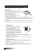
INSTALLATION OF INDOOR AND OUTDOOR UNITS Read completely, then follow step by step. More than 15cm Indoor unit Do not expose the indoor unit to heat or steam. More than 12cm Select a place where there are no obstacles in front or around the unit. Make sure that condensation drainage can More than 12cm be conveniently routed away. More than 2.3m Do not install near a doorway. Ensure that the space on the left and right Fig.1 of the unit is more than 12cm.
Items packed with the unit Number Q ty Name of Accessories 1 Installation Plate 1 2 Clip Anchor 8 3 Self-tapping Screw A ST3.9X25 4 Seal Drain Joint 8 1 5 1 Liquid side 6 Connecting pipe Assembly Gas side 6.35 Parts you must purchase 9.53 ( 9000Btu/h) 12.7 ( 9000Btu/h) 7 Remote controller 1 8 Self-tapping Screw B ST2.9X10 2 9 Remote controller holder 1 Note: Except the above parts provided, the other parts needed during installation you must purchase.
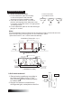
INDOOR UNIT INSTALLATION 1. Fit the Installation Plate 1. Fit the installation plate horizontally on structural parts of the wall with spaces around the installation plate. 2. If the wall is made of brick, concrete or the like, drill eight (8) 5mm diameter holes in the wall. Insert Clip anchor for appropriate mounting screws. 3. Fit the installation plate on the wall with eight (8) type “A” screws. Correct orientation of Installation Plate Fig.
3. Connective Pipe and Drainage Installation Drainage 1. Run the drain hose sloping downward. Do not install the drain hose as illustrated below. Do not form a rise Do not put the hose end into water Fig.6 2. When connecting extension drain hose, insulate the connecting part of extension drain hose with a shield pipe, do not let the drain hose slack. Connective pipe 1. For the left-hand and right-hand piping, remove the pipe cover from the side panel.
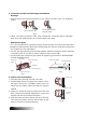
5. Piping and wrapping Bundle the tubing, connecting cable, and drain hose with tape securely, evenly as shown in Fig.10. Because the condensed water from rear of the indoor unit is gathered in ponding box and is piped out of room. Do not put anything else in the box. Indoor unit Connective cable Ponding box Pipe room Connective pipe Wrapping belt Drain hose Fig.10 CAUTION Connect the indoor unit first, then the outdoor unit. Do not allow the piping to let out from the back of the indoor unit.
Settlement of outdoor unit Anchor the outdoor unit with a bolt and nut on a concrete or rigid mount. A Air inlet 10 or Model 8 tightly and horizontally A(mm) B(mm) 458 250 549 549 276 266 9000Btu/h B Air inlet 9000Btu/h Model 12000Btu/h Air outlet Fig.12 Drain joint installation Fit the seal into the drain elbow, then insert the drain joint into the base pan hole of outdoor unit, rotate 90 to securely assemble them.
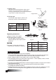
C: Putting nut on Remove flare nuts attached to indoor and outdoor unit, then put them on pipe/tube having completed burr removal.(not possible to put them on after flaring work) Flare nut Copper tube D: Flaring work Firmly hold copper pipe in a die in the dimension shown in the table below. Fig.16 "A" Bar Handle Bar Yoke Outer diam. (mm) 6.35 9.53 12.7 A(mm) Max. 1.3 1.6 1.8 Cone Min. 0.7 1.0 1.0 Copper pipe Clamp handle Red arrow mark Fig.
9000Btu/h 10000Btu/h Input Rated Amp (Switch/Fuse) Power supply Model Model 12000Btu/h 220-240V~ 50Hz or 16A 220-230V ~ 60Hz 16A Power Cord Size 2 1.0mm2 /1.5mm 1.5mm2 NOTE: The supply voltage should be consistent with the rated voltage of the air conditioner. Connect the cable to the indoor unit 1. Indoor/Outdoor connection cable should be H07RN-F type. 2. Open the panel , then remove the window cover. 3. Connect cables according to their marks to terminals. 4.
Connect the cable to the outdoor unit 1. Remove the electric parts cover from the outdoor unit. 2. Connect the connective cables to the terminals as identified with their respective matched numbers on the terminal block of indoor and outdoor units. 3. To prevent the ingress of water, from a loop of the connective cable as illustrated in the installation diagram of indoor and outdoor units. 4. Insulate unused cords (conductors) with PVC-tape.Process them so they do not touch any electrical or metal parts.
AIR PURGING Air and moisture in the refrigerant system have undesirable effects as indicated below: Pressure in the system rises. Operating current rises. Cooling or heating efficiency drops. Moisture in the refrigerant circuit may freeze and block capillary tubing. Water may lead to corrosion of parts in the refrigeration system. Therefore, the indoor unit and tubing between the indoor and outdoor unit must be leak tested and evacuated to remove any noncondensables and moisture from the system.
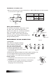
When Using the Vacuum Pump (For method of using a manifold valve, refer to its operation manual.) 1. Completely tighten the flare nuts, A, B, C, D, connect the manifold valve charge hose to a charge port of the low-pressure valve on the gas pipe side. 2. Connect the charge hose connection to the vacuum pump. 3. Fully open the handle Lo of the manifold valve. 4. Operate the vacuum pump to evacuate.
Gas leak check 1. Soap water method: Apply a soap water or a liquid neutral detergent on the indoor unit connection or outdoor unit connections by a soft brush to check for leakage of the connecting points of th piping. If bubbles come out, the pipes have leakage. 2. Leak detector Use the leak detector to check for leakage. Indoor unit check point D C B A Cover Outdoor unit check point CAUTION A: Lo packed valve B: Hi packed valve C and D are ends of indoor unit connection. Fig.
Installation manual