ELECTROLUX MAJOR APPLIANCES OF NORTH AMERICA Technical Service Manual Convertible Refrigerator / Freezer Model FKCH17F7HW REFRIGERATOR/FREEZER SERVICE MANUAL #5995519443 2008 ALL RIGHTS RESERVED
Basic Information Section 1 Basic Information 1-1
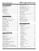
Basic Information Section 1 - Basic Information .............................. 1-1 Table of Contents .................................................... Safe Servicing Practices ........................................ Product Features .................................................... Door Storage .......................................................... Adjustable Door Bins .............................................. Crisper Drawers ......................................................
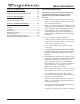
Basic Information Safe Servicing Practices Section 5 - Troubleshooting .............................. 5-1 Troubleshooting Chart .......................................... 5-2 Electronic Control Troubleshooting Chart ............ 5-4 Avoid personal injury and/or property damage by observing important Safe Servicing Practices. Following are some limited examples of safe practices: Section 6 - Wire Diagrams .................................. 6-1 Wiring Diagram ...............................................
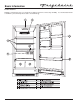
Basic Information Product Features Frigidaire refrigerator/freezers are designed for optimal convenience and storage flexibility. Use the illustration below to familiarize yourself with product features and terminology.
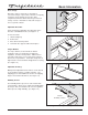
Basic Information Door Storage Door bins, shelves, and racks are provided for convenient storage of jars, bottles, and cans. Frequently used items can be quickly selected. The dairy compartment, which is warmer than the general food storage section, is intended for short term storage of cheese,spreads or butter. Adjustable Door Bins Some models have adjustable door bins that can be moved to suit individual needs. (See Figure 1-1) Figure 1-1. Door Bins To move door bins 1. 2. 3. 4. Lift bin straight up.
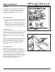
Basic Information Serial Plate The serial plate is located inside the cabinet on the left sidewall. The technician should always refer to the serial plate to assure refrigerant type and quantity, as well as electrical ratings and operating pressures. (See Figures 1-5 and 1-6) Care and Cleaning • • Damp objects stick to cold metal surfaces. DO NOT touch interior metal surfaces with wet or damp hands. The freezer must be unplugged (to avoid electrical hazard) from power source when defrosting the unit.
Electronic Control Section 2 Electronic Control 2-1
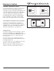
Electronic Control Electronic Temperature Control The electronic temperature controls are located on the evaporator cover in the upper right hand corner. (See Figure 3-1) The rocker switch controlling the mode of operation is mounted to the top of the evaporator cover. (See Figure 3-2) Temperature is factory preset to provide satisfactory food storage temperatures. Freezer Control The initial temperature setting "4" is displayed when power is applied the very first time.
Electronic Control Operation of Electrical Control Components Freezer and Refrigerator Modules The modules, when selected by the rocker switch, control the temperature of the unit by an internal thermistor mounted on the circuit board. Each module has an individual service mode.
Electronic Control Service Diagnostic Mode Initiate Service Mode The refrigerator and freezer controls have individual service modes. Each control assembly has a thermistor embedded on the electronic control assembly circuit board. To initiate service mode for the refrigerator or freezer control, set the control to “4” then press and hold the UP and DOWN buttons for 3 seconds until the display changes to "8".
Electronic Control Error Indication The following error conditions are monitored by each electronic control assembly: 1. Thermistor open or shorted. A defective thermistor will require that the affected electronic control assembly be replaced. 2. Stuck Key (the key appears to be pressed for longer than 30 seconds). 3. Low Voltage (AC line voltage has dropped below 90 volts). If any of these errors occur, the display will flash an "E" at one second intervals and the control will go into Fail Safe Mode.
Electronic Control Notes 2-6
Refrigeration System Section 3 Refrigeration System 3-1
Refrigeration System Safety Warnings Instructions given here are furnished as a guide. Persons attempting to use these instructions to make repairs to the sealed refrigeration system should have a working knowledge of refrigeration and previous training on sealed system repair, and an EPA certification for servicing refrigeration systems. Compressor Testing Whenever testing a compressor, extreme caution should be used to prevent damaging the terminals.
Refrigeration System Basic Components WEAR APPROVED SAFETY GLASSES WHEN WORKING WITH OR ON ANY PRESSURIZED SYSTEM OR EQUIPMENT. HAVE AN APPROVED DRY TYPE FIRE EXTINGUISHER HANDY WHEN USING ANY TYPE OF GAS OPERATED TORCH. The basic components of a refrigerator/freezer are a compressor, condenser, evaporator, heat exchanger (capillary tube and suction line) and drier. Refrigerant Cycle The refrigerant cycle is a continuous cycle that occurs whenever the compressor is in operation.
Refrigeration System Low/High Side Leak or Undercharge Testing for Refrigerant Leaks A loss of refrigerant can result in any of the following: The line piercing valve (clamp-on type) should be used for test purposes only. It must be removed from system after it has served its purpose. 1. Excessive or continuous compressor operation. 2. Above normal refrigerator/freezer compartment temperature. 3. A partially frosted evaporator (depending on amount of refrigerant loss). 4.
Refrigeration System To Use Refrigerant To Flush The System: To Flush The System Use extreme care when using Dry Nitrogen to flush systems. Pressure in nitrogen cylinder could be as high as 2000 psi. Nitrogen cylinder must be equipped with approved pressure regulator and pressure relief valve. Ensure that your hoses have adequate ratings for pressure involved and that all of your equipment is in good condition.
Refrigeration System Installing a New Compressor The following instructions are generalized to help the technician understand the procedures of sealed system repairs. See Section 5 Component Teardown on the exact steps of accessing the components of the refrigeration system. Entirely new compressors have been developed for use with R-134a and Ester oil refrigeration systems. Both compressor and electric motor have been modified.
Refrigeration System 10. Reform both suction and discharge lines to align with new compressor. If they are too short, use additional lengths of tubing. Joints should overlap 0.5” to provide sufficient area for good solder joint. Clean and mark area where tubing should be cut. Cut tubing with tubing cutter. Work as quickly as possible to avoid letting moisture and air into the system. 11. Solder all connections according to soldering procedure. 12. Remove original filter-drier.
Refrigeration System Filter-Drier Installation Evaporator and Suction Line Replacement Any time the sealed system is opened and the refrigerant charge is removed, the liquid line filter-drier must be replaced and the system thoroughly evacuated before replacing refrigerant. The following instructions are generalized to help the technician understand the procedures of sealed system repairs. See Section 5 Component Teardown on the exact steps of accessing the components of the refrigeration system.
Refrigeration System Equipment Needed for Evacuation & Recharging: Check the serial plate for the correct refrigerant type. It is extremely important to verify the type of refrigerant in the system before starting any sealed system repairs. With the possible exception of the vacuum pump, all service equipment that comes in contact with R-134a during evacuation and recharging must be dedicated.
Refrigeration System R-134A SYSTEMS ARE PARTICULARLY SUSCEPTIBLE TO MOISTURE CONTAMINATION WHICH CAN ONLY BE PREVENTED BY EVACUATING THE SYSTEM FOR A MINIMUM OF 30 MINUTES TO ATTAIN A MINIMUM 29.9 INCH (500 MICRON OR LOWER) VACUUM. 7. Leak test low-side. Close compound gauge. Run compressor for a few minutes and leak test high-side. When leak is found, recapture refrigerant using EPA approved recovery system. Repair and go back to step 1.
Refrigeration System 10. Slowly open the high-side manifold gauge valve to allow the compressor to remove any refrigerant trapped in the high-side hose and the process fitting. 11. Close both of the manifold gauge valves. If the high-side gauge reading rises, the pinch-off must be corrected before proceeding. 12. Remove the high-side process tube adapter and solder the process tube closed. 13. Clamp the low-side process tube with the pinch-off tool while the unit is running.
Refrigeration System R-134a Refrigeration Systems Instructions given here are furnished as a guide. Persons attempting to use these instructions to make repairs to the sealed refrigeration system should have a working knowledge of refrigeration and previous training on sealed system repair. Verify Refrigerant Type In The System R-134a and R-12 are completely incompatible.
Refrigeration System For example, hoses that were used for a refrigeration system operating on R-12 may contain small quantities of mineral oil which can block the capillary tube in a system operating on R-134a. As little as one milligram may be sufficient to cause a blockage. In addition, sealed system components that have been used with CFC systems must not be used with R-134a systems. These components may contain residual amounts of refrigerant and oil which could damage an R-134a system.
Refrigeration System Vacuum Pump Maintenance Refrigerant Leaks It is absolutely essential to maintain your vacuum pump according to the manufacturer’s instructions including required oil changes at the recommended intervals. Vacuum pump oil should always be changed after evacuating a contaminated system. Vacuum pump performance should be checked periodically with a micron gauge. A system with R-134a and Ester oil will become saturated with moisture much faster than a system with R-12 and mineral oil.
Refrigeration System Leak Detection R-134a system leaks can be pinpointed by means of an electronic leak detector or by bubble solution. Electronic leak detectors for R-134a service are currently available from several manufacturers. The least expensive models are non-selective detectors that will detect any type of emission or vapor present, regardless of its chemical composition. Some non-selective detectors designed for use with R-12 may have a much lower sensitivity when used with R-134a.
Refrigeration System HFC-134a, CFC-12 Pressure Temperature Chart 3-16
Refrigeration System Inhalation Toxicity Spills or Leaks HFC-134a poses no acute or chronic hazard when it is handled in accordance with DuPont recommendations and when exposures are maintained at or below the DuPont Acceptable Exposure Limit (AEL) of 1,000 ppm (8 and 12 hour Time-Weighted Average or TWA). If a large release of vapor occurs, such as from a large spill or leak, the vapors may concentrate near the floor or low spots and displace the oxygen available for breathing, causing suffocation.
Refrigeration System Combustibility of HFC-134a Filling and Charging Operations HFC-134a is nonflammable at ambient temperatures and atmospheric pressure. However, tests have shown HFC-134a to be combustible at pressures as low as 5.5 psig (139.3 kPa absolute) at 177°C (350°F) when mixed with air at concentrations generally greater than 60% volume air. At lower temperatures, higher pressures are required for combustibility.
Component Teardown Section 4 Component Teardown 4-1
Component Teardown COMPONENT TEARDOWN This section explains how to access and remove components from a Frigidaire Refrigerator/Freezer, and has been arranged in such a way as to simulate which components would need to be removed first in order to gain access to other components. When following a component removal procedure, it may be necessary to reference another component removal procedure listed earlier in this section.
Component Teardown Exterior Components Handle Assembly Door Handle Removal Set Screw The door handle is secured to the door assembly with two set screws in the door handle that clamp the door handle to the handle mounting shoulder screws mounted on the door assembly. (See Figure 5-1) To remove the door handle: 1. Using a 3/32” allen wrench, extract the set screw from each end of the door handle. 2. Pull door handle off handle mounting shoulder screws.
Component Teardown Door Stop Removal Door Frame The door stop is mounted to the underside of the door assembly and secured in position with two flat head screws. Screws Door Stop To remove the door stop: 1. Remove door from unit. 2. Extract the two screws securing the door stop to the bottom of the door assembly. (See Figure 5-5) Door Gasket and Inner Panel Removal The inner panel of the door assembly is secured with screws that pass through the inner panel and fasten into the door assembly.
Component Teardown Gallon Door Bin Removal Bend In Here The gallon door bin has slots on each end that fit over molded slots in the door liner. To remove the gallon door bin, bend the inside lip of the gallon door bin away from the supports molded into the door liner while pulling out of the door. (See Figure 5-7) Gallon Door Bin Figure 5-7. Gallon Door Bin Removal Two Liter Door Bin Removal There are four two liter door bins that can be arranged as needed by the user.
Component Teardown Door Switch Removal Access Hole The door switch is mounted inside a hole in the cabinet base along the lower right hand side. (See Figure 5-10) Wire Terminals To remove the door switch: 1. Remove kickplate. 2. Reach into the access hole next to the door switch and disconnect the electrical leads from the door switch terminals. 3. Press in on the retaining latch on the switch body and push switch through hole in cabinet base. Door Switch Figure 5-10.
Component Teardown Crisper Cover Assembly Removal Crisper Cover Support LH The crisper cover assembly slides into a slot formed in the left and right hand supports that are secured with screws to the liner sidewall. Crisper Cover Support RH Screws Humidity Control LH To remove the crisper cover assembly: 1. Remove crisper drawers from unit. 2. Reach under the crisper cover and lift up on the crisper cover glass insert. Remove glass insert from unit. (See Figure 5-13) 3.
Component Teardown Baffle Plate Removal The baffle plate is secured with four retaining latches to slots in the compartment upper back wall. (See Figure 5-15) To remove the baffle plate, with one hand grab the baffle plate from the center and pull back while with the other hand, reach behind to disengage the retaining latches. Baffle Plate Figure 5-15. Baffle Plate Removal Evaporator Cover Removal Gasket The evaporator cover is secured with screws to the back wall and bottom of the freezer compartment.
Component Teardown Electronic Control Removal Control Switch Refrigerator Control The electronic control is secured to a housing with four retaining latches on the inside of the evaporator cover. The housing has air holes for the thermistors mounted on the circuit board. Disconnect Here To remove the electronic controls: 1. Remove or pull back evaporator cover to access the controls. 2.
Component Teardown Defrost Thermostat Removal Disconnect Here The defrost thermostat is secured with a retaining clip to the upper left corner of the evaporator assembly. To remove the defrost thermostat: Defrost Thermostat 1. Remove the evaporator cover. 2. Disconnect the defrost thermostat wire leads from the wire harness. (See Figure 5-20) 3. Pull the defrost thermostat off of the evaporator tubing. Defrost Heater Removal Figure 5-20.
Component Teardown Compressor Area Components Electrical Connection Power Cord Removal The power cord enters the compressor area on the lower left side and is secured to the compressor mounting plate with a P-clamp and screw. Ground Screw To remove the power cord: 1. Pull unit from its installation position to access the rear compressor area. 2. Using a phillips head screwdriver, extract the four screws securing the compressor area shield to the rear of the unit. Remove shield. 3.
Component Teardown Compressor Removal The compressor sits on four grommets and is secured with four screws to the compressor mounting plate. (See Figure 5-25 & 5-26 ) Capacitor Ground Wire To remove the filter-drier: 1. Pull unit from its installation position. 2. Extract the screws securing the compressor shield to the unit frame and remove from unit. 3. Using a small flat bladed screwdriver, release the locking tab from the wire harness connection and disconnect from compressor controller. 4.
Component Teardown Drain Pan and Drain Pan Heater Loop Removal Screws The drain pan heater loop is clamped to the drain pan with two brackets and secured with screws. The drain pan is secured with four screws to the underside of the unit frame. Drain Pan Heater Loop To remove the drain pan heater loop: 1. Pull unit from its installation position. 2. Using a short phillips head screwdriver, extract the four screws securing the drain pan heater loop brackets to the drain pan. (See Figure 5-27) 3.
Component Teardown Condenser Service The condenser is foamed in place and is not accessible for repair. However, repair can be made by installing a service replacement condenser kit. Refer to the part list of the model being serviced for the correct kit part number. Each service replacement condenser kit consists of a condenser assembly that can be installed on the back of the cabinet, mounting hardware, replacement filter-drier and a complete installation instructions.
Troubleshooting Section 5 Troubleshooting 5-1
Troubleshooting Cause Problem Refrigerator/Freezer compressor does not run. Correction Refrigerator/Freezer is plugged into a circuit that has a ground fault interrupt. Use another circuit. Check circuit for proper voltage. Temperature control is in the "OFF" position. Set control to a temperature setting. Instruct customer. Refrigerator/Freezer may not be plugged in, or plug may be loose. Ensure plug is tightly pushed into outlet. House fuse blown or tripped circuit breaker.
Troubleshooting Problem Cause Louder sound levels whenever Refrigerator/Freezer is on. Modern Freezers have increased storage capacity and more stable temperatures. They require heavy duty compressors. This is normal. When the surrounding noise level is low, you might hear the compressor running while it cools the interior. Louder sound levels when compressor comes on. Refrigerator/Freezer operates at higher pressures during the start of the ON cycle. This is normal.
Troubleshooting The following table relates to troubleshooting the electronic control and associated components. Problem Compressor and evaporator fan motor does not run. Cause Correction 1. Do any of the LED’s on the control illuminate? Yes. Go to step 2. No. Check power to freezer and make sure unit is plugged in. Check rocker switch. 2. Is the selector (rocker) switch on the evaporator panel set to the middle position. Yes. Select refrigerator or freezer on switch.
Troubleshooting Problem Freezer does not automatically defrost. Cause Correction 1. Program the control for a manual defrost. Does the defrost operate? Yes. Replace electronic control. No. Go to step 2. 2. Disconnect the orange wire from the defrost thermostat and the white wire from the defrost heater. Measure the resistance between the wire on the thermostat and the wire at the end of the heater. Is the reading about 25 omhs? Yes. Replace electronic control. No. Go to step 3. 3.
Troubleshooting Notes 5-6
Wiring Diagrams Section 6 Wiring Diagrams 6-1
Wiring Diagrams 7 4 6-2 8 3 6 5 2 1
Wiring Diagrams Thermistor Resistance Chart Temp °C Temp °F 0° 32° Nominal Resistance Ohms 32,654 Max. Ohms Min. Ohms 33,604.72 31703.29 Tolerance % +/2.91 -15° 5° 72,940 75,283.21 70,596.79 3.21 -20° -4° 97,060 100,283.44 93,836.56 3.32 -30° -22° 177,000 183,293.70 170,706.30 3.55 -40° -40° 336,000 349,139.51 322,860.49 3.
Installation Information Section 7 Installation Information 7-1
Installation Information IMPORTANT SAFETY INSTRUCTIONS Safety Precautions Do not attempt to install or operate this appliance until you read the safety precautions in this guide. Safety items throughout this guide are labeled with a Warning or Caution based on the risk type. WARNING indicates a potentially hazardous situation which, if not avoided, could result in death or serious injury. Caution indicates a potentially hazardous situation which, if not avoided, may result in minor or moderate injury.
Installation Information DESTROY CARTON, PLASTIC BAGS, AND ANY EXTERIOR WRAPPING MATERIAL IMMEDIATELY AFTER THE REFRIGERATOR/FREEZER IS UNPACKED. CHILDREN SHOULD NEVER USE THESE ITEMS FOR PLAY. CARTONS COVERED WITH RUGS, BEDSPREADS, PLASTIC SHEETS OR STRETCH WRAP MAY BECOME AIR TIGHT CHAMBERS AND CAN QUICKLY CAUSE SUFFOCATION. A CHILD MIGHT SUFFOCATE IF HE CRAWLS INTO THE FREEZER TO HIDE OR PLAY. REMOVE THE DOOR/LID OF THE REFRIGERATOR/FREEZER WHEN NOT IN USE, EVEN IF YOU PLAN TO DISCARD THE FREEZER.
Installation Information Location 1. Choose a place that is near a grounded electrical outlet. Do Not use an extension cord or an adapter plug. 2. If possible, place the refrigerator/freezer out of direct sunlight and away from the range, dishwasher or other heat sources. 3. The refrigerator/freezer must be installed on a floor that is level and strong enough to support a fully loaded refrigerator/freezer. 4. Consider water supply availability for models equipped with an automatic ice maker. 5.
Installation Information Electrical Information These guidelines must be followed to ensure that safety mechanisms in the design of this refrigerator/freezer will operate properly. Refer to the serial plate for correct electrical rating. The power cord of the freezer is equipped with at threeprong grounding plug for protection against shock hazards. It must be plugged directly in to its own properly grounded three-prong receptacle, protected with a 15 amp time delay fuse or circuit breaker.
Installation Information Door Removal Hinge Cover For some installations it may be necessary to remove the door to fit through the entrance of the installation site. Hex Head Screws To remove the door, follow the steps below. 1. Make sure electrical plug is disconnected from the wall outlet. Hinge Plate 2. Gently lay freezer on its back on a soft clean surface. 3. Lift plastic cover off upper hinge assembly. (See Figure 7-4) Figure 7-4. Top Hinge Removal 4.
Installation Information Model FKCH17F7HW Unit Dimensions ¾ ⅛ ⅛ 7-7
Installation Information Notes 7-8